- Stereo FM band receiver with RDS decoding for mobile applications.
- Continuous full RDS data output through RS232: RDS PS, PI, TA/TP/TMC, CT, TMC.
- Full Radio Text supported: 2×64 characters.
- Raw TMC data output.
- Low power operation with two AA (HR6) 1V2 Ni-Mh batteries or power supply.
- Power input range is +2.4V … +3.0V, 50..60mA without OLED and 80..90mA with OLED.
- Runs on a PIC18F46K20 at 16 MhZ.
- Full user control (volume, tune, save preset) with a 5-way micro joystick.
- Module works as stand-alone without OLED as well.
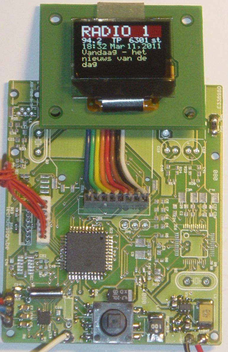
- Optional OLED Module 1 with RGB OLED 96×64 pixels shows PS (station name), frequency, TA/TP/TMC, PI, mono/stereo, RT (2 alternating lines of radio text)
- Serial interface control so the module may be used as a stand-alone module.
- Analog line stereo output.
- Antenna connection, suggest use of a 30cm -> 2m wire.
- Assembled and fully tested KIT1 now available.
- Project source code can be purchased separately.
Circuit explanation / Getting started:
| PIC18F46k20 | The 18F46k20 offers high speed and low power operation. Well suited for a portable application such as this one. | |
| Si4731/4735 | Small tuner chip, includes a RDS demodulator. | |
| OLED | OLED Module 1 with 96×64 pixels RGB OLED, Size: 0.95″Needs a +14V Vdd, this is generated by a TPS61080. | |
| Controls | With the micro joystick, there are several user controls available. Two for volume (up & down) , tune (left & right) and save preset (short enter.) Zone can be selected on boot:Zone 1 (USA): FM 87,50 -> 108.0 MhZ (75µS setting) To select this zone: left joystick and release on bootup or restart. Zone 2 (EURO): FM 87,50 -> 108.0 MhZ (50µS setting): Up joystick. Zone 3 (JAPAN): FM 76,0 -> 108.0 MhZ (50µS setting): Right joystick. Serial interface: tune up and down (tup & tdn) , set frequency (setxxx.x), save preset (sav), get frequency (get), show basic rds info (rds ), reset module (res) Preset and zone are stored and reloaded on reboot. | |
| Power | The MCP1640 DC-DC step-up converter makes it possible to power the whole circuit from only one AA battery. We have chosen two AA batteries for enhanced stability and endurance. Power input range is +2.4V … +3.0V Do not exceed this! | |
| PCB: | We used as much SMD-parts as possible. The PCB from our shop is a double sided and 100% connection tested PCB with plated-through-hole connections. All holes are drilled already. PCB size = 66,50 x 54.90 mm |
Schematics: (eagle-files and library can be downloaded below.)
Full resolution image: schematic and pcb (GIF format) Right-click and save as, then open in an image viewer (sch is too large for some browsers.)
Bill of Materials (Parts List)
Important note: The following sections from the schematic are not needed in this particular setup, and are left out on assembly: EE_PROG, USB+SD, MP3, ACCELERATOR.
For more detail: FM RDS Tuner Module for mobile applications using PIC18F46k20