Summary of FM RDS Tuner Module for mobile applications using PIC18F46k20
This article describes a portable Stereo FM band receiver with RDS decoding for mobile use. Powered by two AA batteries or a 2.4V–3.0V supply, it features a PIC18F46K20 microcontroller and Si4731/4735 tuner chip. The system supports full RDS data output via RS232, including Radio Text and TMC. It includes an optional 96x64 RGB OLED display and is controlled via a 5-way micro joystick. The module functions as a standalone unit or with serial interface control, offering analog stereo output and customizable frequency zones for USA, Europe, and Japan.
Parts used in the Stereo FM Band Receiver with RDS Decoding:
- PIC18F46K20 Microcontroller
- Si4731/4735 Tuner Chip
- OLED Module 1 (96x64 pixels RGB)
- TPS61080 Voltage Regulator
- MCP1640 DC-DC Step-Up Converter
- 5-Way Micro Joystick
- Two AA (HR6) Ni-Mh Batteries
- RS232 Serial Interface
- Analog Line Stereo Output
- Antenna Wire (30cm to 2m)
- Stereo FM band receiver with RDS decoding for mobile applications.
- Continuous full RDS data output through RS232: RDS PS, PI, TA/TP/TMC, CT, TMC.
- Full Radio Text supported: 2×64 characters.
- Raw TMC data output.
- Low power operation with two AA (HR6) 1V2 Ni-Mh batteries or power supply.
- Power input range is +2.4V … +3.0V, 50..60mA without OLED and 80..90mA with OLED.
- Runs on a PIC18F46K20 at 16 MhZ.
- Full user control (volume, tune, save preset) with a 5-way micro joystick.
- Module works as stand-alone without OLED as well.
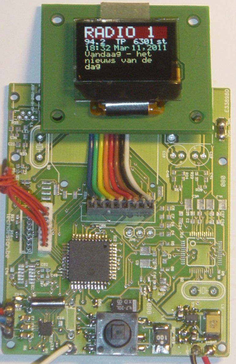
- Optional OLED Module 1 with RGB OLED 96×64 pixels shows PS (station name), frequency, TA/TP/TMC, PI, mono/stereo, RT (2 alternating lines of radio text)
- Serial interface control so the module may be used as a stand-alone module.
- Analog line stereo output.
- Antenna connection, suggest use of a 30cm -> 2m wire.
- Assembled and fully tested KIT1 now available.
- Project source code can be purchased separately.
Circuit explanation / Getting started:
| PIC18F46k20 | The 18F46k20 offers high speed and low power operation. Well suited for a portable application such as this one. | |
| Si4731/4735 | Small tuner chip, includes a RDS demodulator. | |
| OLED | OLED Module 1 with 96×64 pixels RGB OLED, Size: 0.95″Needs a +14V Vdd, this is generated by a TPS61080. | |
| Controls | With the micro joystick, there are several user controls available. Two for volume (up & down) , tune (left & right) and save preset (short enter.) Zone can be selected on boot:Zone 1 (USA): FM 87,50 -> 108.0 MhZ (75µS setting) To select this zone: left joystick and release on bootup or restart.
Zone 2 (EURO): FM 87,50 -> 108.0 MhZ (50µS setting): Up joystick. Zone 3 (JAPAN): FM 76,0 -> 108.0 MhZ (50µS setting): Right joystick. Serial interface: tune up and down (tup & tdn) , set frequency (setxxx.x), save preset (sav), get frequency (get), show basic rds info (rds ), reset module (res) Preset and zone are stored and reloaded on reboot. |
|
| Power | The MCP1640 DC-DC step-up converter makes it possible to power the whole circuit from only one AA battery. We have chosen two AA batteries for enhanced stability and endurance. Power input range is +2.4V … +3.0V Do not exceed this! | |
| PCB: | We used as much SMD-parts as possible. The PCB from our shop is a double sided and 100% connection tested PCB with plated-through-hole connections. All holes are drilled already. PCB size = 66,50 x 54.90 mm |
Schematics: (eagle-files and library can be downloaded below.)
Full resolution image: schematic and pcb (GIF format) Right-click and save as, then open in an image viewer (sch is too large for some browsers.)
Bill of Materials (Parts List)
Important note: The following sections from the schematic are not needed in this particular setup, and are left out on assembly: EE_PROG, USB+SD, MP3, ACCELERATOR.
For more detail: FM RDS Tuner Module for mobile applications using PIC18F46k20
- How does the device handle power consumption?
The device operates on low power using two AA batteries or a power supply within the +2.4V to +3.0V range. - Can the module function without the OLED screen?
Yes, the module works as a stand-alone unit without the OLED display. - What microcontroller runs this project?
The project runs on a PIC18F46K20 operating at 16 MHz. - How can users select different frequency zones?
Users can select zones by pressing specific joystick directions during bootup: left for USA, up for EURO, and right for JAPAN. - Does the receiver support Radio Text?
Yes, it fully supports Radio Text with 2 alternating lines of 64 characters each. - What type of antenna is suggested for operation?
A wire between 30cm and 2m is suggested for the antenna connection. - Is the MCP1640 used for voltage conversion?
Yes, the MCP1640 is a DC-DC step-up converter that allows the circuit to run from a single AA battery. - How are presets managed on the device?
Preset and zone settings are stored and automatically reloaded upon reboot.