Summary of Sensor Modules
Simple, informative sensor modules with clear PCB markings that show voltage range, sensor name, I2C read/write addresses, pinout labels, and a graphic of expected sensor outputs. Initial modules include MPU6050 (3-axis gyroscope, 3-axis accelerometer, temperature), SHT10 (humidity, temperature), and HMC5883 (3-axis magnetometer/compass), designed to speed prototyping and avoid searching datasheets.
Parts used in the Sensor Modules:
- MPU6050 sensor IC (3-axis gyroscope, 3-axis accelerometer, temperature)
- SHT10 sensor IC (humidity and temperature)
- HMC5883 sensor IC (3-axis magnetometer, compass)
- Custom PCB with silk-screen markings (voltage range, sensor name, I2C addresses, pinout labels)
- I2C header pins
- PCB graphic/icons representing sensor outputs
Sensor Modules
It’s been a long time since I’ve post a new hobby project of mine! I decided that is time to upload a new one! Like my Sensor Stick module this project will be about sensors as well.
You can find multiple modules out there with various sensing ICs that almost all of them look exactly the same! They are ugly and without properly markings on their surface.
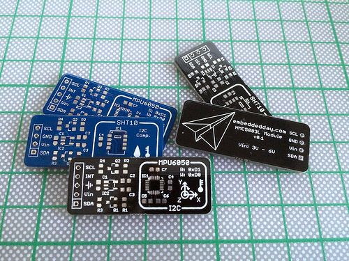
For example, some of those don’t have the input voltage range on the PCB or the pin out names or even the sensor address (in the case of a digital I2C sensors for example). In order to find that info, you have to download files, unzip them, look the schematics of the module then the datasheet of the sensor etc. A time consuming method especially for a quick and dirty prototype!
So, I think that there is a better way! You just have to pay a little bit attention on the PCB creation process and most of those time delay factors are gone. And this is the result:
Simple, yet informative sensor modules that will fast track your next project! And yes, they look beautiful!
On the PCB you will find a clear indication for the voltage range, the sensor name for quick searching, the read and write I2C addresses together with the pin out labeling. On top of those, a graphic representation of the sensor measuring values gives a better understanding of what you should expect as an output.
For now, I’ve made sensor modules for the MPU6050 sensor (3-axis gyroscope, 3-axis accelerometer, temperature sensor), the SHT10 sensor (humidity, temperature) and the HMC5883 sensor (3-axis magnetometer, compass). Hopefully more ICs will get this treatment soon!
For more detail: Embeddedday.com – Sensor Modules
- What problem do these sensor modules solve?
They eliminate time spent hunting datasheets by providing clear PCB markings for voltage range, sensor name, I2C addresses, and pinouts. - Which sensors have been made into modules so far?
MPU6050, SHT10, and HMC5883 modules are available. - What information is printed on the PCB?
Voltage range, sensor name, read and write I2C addresses, pinout labeling, and a graphic of expected sensor values. - How do the PCBs help with prototyping?
They provide immediate reference info on the board so you do not need to open files or datasheets for quick prototypes. - Do the modules include a visual of sensor outputs?
Yes, each PCB includes a graphic representation of the sensor measuring values. - Are the modules designed to look different from typical sensor boards?
Yes, they are designed to be simple, informative, and aesthetically improved compared to many existing modules. - Does the project plan to add more ICs?
Yes, the author hopes to treat more ICs similarly in the future.