The design uses the PIC18F series microcontroller. All the control functionalities of the system are built around this. Upgradeability is the unique feature of this system. Control card hardware and software allows the manufacturer to add or remove the features as per customer requirement and model. Thus once the whole system is designed it is very economic in large quantity production. Single-phase motor is considered for the design. Front panel consists of a keypad and LCD display. Keypad provides automatic and manual wash options to the user. LCD display is convenient to convey machine information to user. One more design possibility is to use brushless DC motors or three phase induction motor. These types of motors are very efficient but requires complex control algorithm. To implement such a complex and real time algorithm dedicated controller and software is required which a master controller controls. Even though cost is important criteria modern washing machines are designed with BLDC motors owing to efficiency and energy conservation. But in this assignment single phase universal motor has been used to design prototype due to its simplicity.
Design Specifications
This include both hardware and software specifications.
- The system should provide fully automatic mode, semi-automatic mode and manual mode. Modes should be selectable by a keypad.
- Under fully automatic mode user intervention requirement should be zero. Once the system is started in this mode it should perform its work independently and after the completion of work it should notify the user about the completion of work. This mode instantaneously should sense cloth quality and requirement of water, water temperature, detergent, load, wash cycle time and perform operation accordingly.
- In semi-automatic mode also user requirement should be nil. But user has to choose any one of the semi-automatic mode in which washing conditions are predefined. Once the predefined mode is started the system should perform its job and after completion it should inform the user.
- In manual mode continuous intervention of user is required. User has to specify which operation he wants to do and has to provide related information to the control system. For example, if user wants to wash only, he has to choose ‘wash’ option in manual mode. Then the system should ask the user to enter the wash time, amount of water and the load. After these data are entered, the user should start the machine. When the specified operation is completed system should inform the user.
- When the lid is open system should not work. If door is accidentally opened in between wash operation, then the system should stop working in minimum possible time (<10s)>
- The system should provide all basic features of a washing machine like washing, rinsing, spinning, drying, cold wash, hot wash etc.
- The system should provide easy options for upgradeability of new features. The hardware and the software should be compatible to both machines, which have fewer features, or more features. Removal of any feature should not affect the working of any other features or overall working of the system.
- The system should work on single phase AC from 190VAC to 250VAC. The system should protect itself from power supply voltage variations.
- In the event of power failure, the washing machine should automatically start its cycle from the point of interruption when power is resumed.
Hardware Design
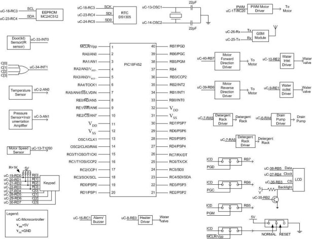
Heart of this system is PIC18F452. Most of the peripheral features have been utilized to implement the design. Controlling the motor is very crucial part of the design. The PWM feature of the microcontroller controls motor speed. PWM output is fed to driver circuit and then to motor. To rotate the motor in two different directions ‘forward’ and ‘reverse’ direction control blocks are used. Motor speed sensor is interfaced to microcontroller. Microcontroller reads the speed of the motor and appropriately controls the speed of the motor in different phases of washing using PWM output. Door sensor, pressure sensor, keypad are also interfaced to microcontroller. Serial port in connected to GSM module. EEPROM and RTC are interfaced to MSSP module of controller. In circuit serial programming facility is provided for quick and easy programming and debugging.
Schematic Design
A detailed schematic with pin connection of PIC microcontroller is provided in the Figure (1).
Figure (1) Block Schematic of Washing Machine Controller
Washing machine default parameters and user settable parameters are stored in external EEPROM. Internal EEPROM of the PIC is used to store status of the washing machine. The status is regularly logged to the internal EEPROM. In the event of power failure or whenever program resets, status flags are read from the internal EEPROM and thus status of the machine is determined and operation is continued from the point of interruption. Accessing of internal EEPROM is faster compared to external EEPROM. PIC18F452 provide 256 bytes of internal EEPROM that is not sufficient for storing parameters of machine. For this purpose external EEPROM is used. Depending on the mode flag and status flag conditions corresponding machine parameters are read from the external EEPROM and temporarily stored in RAM and operations are performed.
RTC DS1305 is interfaced to SPI port of the microcontroller. This RTC is used as timing reference for all timing calculation of machine. Whenever a particular mode starts RTC is initialized to zero and there onwards RTC is read and compared with the set timings; with the battery backup provision actual RTC can also be implemented. Since PIC allows either I2C or SPI mode at a time, whenever we need to access EEPROM or RTC, MSSP port of the PIC has to be configured to respective protocol.
In Circuit Serial Programming (ICSP) is accomplished using pins PGM, PGC, PGC and active low MCLR. These pins are also used to RB5, RB6 and RB7. To satisfy both conditions jumpers are provided. When programming of IC is required jumper settings ‘1’ has to be used. After programming, jumpers have to be replaced to setting ‘2’. This allows the use of RB5 to RB7 and brings the controller from programming mode to normal working mode. Thus ICSP helps speedy programming and debugging of software.
Some of the sensor outputs are fed to instrumentation amplifier to bring the output level to 0V to 5V range. Door (lid) sensor is connected to external interrupt 0. High priority is assigned to this interrupt. Thus opening of the door causes triggering of INT0 and INT0 ISR immediately stops the machine and informs the user. Analog input channels AN2, AN3 and AN4 can be used to upgrade the system with additional sensors.
Keypad is connected to PORTD. Keypad and meaning of keys are shown in Figure (2). Pull-up resistors are connected to RD0 to RD3 to enable keypad press detection. ORing RD4 to RD7 achieves this and output is given to external interrupt 1(INT1). When any of the keys is pressed ORed output becomes high and INT1 triggers. INT1 ISR does a keypad scan and appropriately performs the operation.
Motor speed sensor is given to T1CKI, which is an external clock input to timer1/timer3. Timer is configured in counter mode for calculating the speed. Speed is calculated by counting pulse output from the sensor for one second.
Figure (2) Keypad and Key Functions
Motor direction driver circuit determines the direction of the motor. Motor forward direction drives the current in forward direction and motor rotates forward. Motor reverse direction driver does the opposite of it. Software has to take care that both are not activated at a time. Speed of the motor is controlled using PWM driver. Speed of the motor and hence the drum varies in different phases of washing cycles. Speed profile of the washing machine drum is illustrated in Figure (3). Before changing the direction of the motor, PWM output must be made zero. PWM output is varied as per the calculated speed to maintain constant speed during wash cycles.
Figure (3) Speed Profile of Different Washing Cycles
Port pins RE1 and RE2 are fed to water valve drivers, which control the flow of water, while RE0 is connected to heater relay. Dedicated LCD with 3-wire interface is used. 3 wires consist of data line, clock and Chip Select (CS). Backlight control is also provided. GSM module is interfaced using serial port. Standard AT command set is used to communicate with GSM module.
It is assumed that when sensor outputs reach microcontroller inputs it has maximum swing of 0V to 5V. It is also assumed that PWM driver circuit controls gearbox and clutch mechanisms. Power supply circuits and regulators are not shown in the Figure (1). Suitably designed SMPS and AC regulators take care of power supply requirement of each block.
Software Design
Based on the specification and hardware design flowchart/algorithm/pseudo code for the software can be designed. The overall flow of the software is shown in Figure (4). To maintain modularity and for easy understanding machine functionalities are divided into functions. Name of different functions and what each function does has been briefly defined bellow:
- def.h: header file; this file includes all port pin definitions, global variable declarations, address assignments, macro definitions, function prototypes.
- INT0 ISR: external interrupt service routine; has highest priority; door sensor output is connected to it; a low to high transition triggers the interrupt; if machine is running immediately stops and alarms; if machine is not running it won’t start unless lid is closed (sensor output goes low); message is sent to user in both conditions; alarm activated.
- INT1 ISR: external interrupt 1; has second priority; keypad activity is detected here; calls scan_keypad() routine; as per keypad activity sets the parameter and initializes the activity; One of the crucial software routines.
- Serial ISR: occurrence of this interrupt means that a command is received at GSM sent by the user; ISR reads the message from the GSM module and sets the parameters; initializes the activity accordingly; sends back status/acknowledgement to user. Used functions: read_from_GSM(), write_to_GSM().
- fully_automatic_mode(): clothe quality is instantaneously sensed(stain sensor installed) and amount of water, wash cycles and timing requirements are optimized; accordingly parameters are set and activities are initialized and monitored till the completion of work. Used functions: most of the functions
- semi_automatic_mode(): activated by keypad scan routine; displays predefined semi_auto1() to semi_auto_n() modes; can be scrolled up or down by the user; after the mode is selected and entered by the user sets the parameter and initializes the activities; then transfers the control to monitor_keypad() routine.
- manual_mode(): activated by monitor_keypad(); upon entering it asks the user to enter different parameters like water level, water temperature, wash time. After receiving the parameters it waits for ‘E’ button to be pressed for starting the operation; provides options like wash, rinse, spin, drain; options can be selected by scrolling up or down. Used functions: rins(),wash(), spin(), drain(), check_water_temperature().
- fill_tub(): input:amount of water to be filled; return: none; activates water inlet; checks for water level by reading pressure sensor and calibrating it; if filled water=amount of water to be filled exit the function else continue.
- wash(): input: total wash time, tumble wash time; return: none ;reads RTC; calls the tumble_wash() routine to perform tumble wash and passes the tumble wash time to this routine; if wash time is over exit function else repeat the process; used functions: tumble_wash(), read_RTC().
- rinse(): input : rinse time, motor speed; return: none; reads RTC; as per received motor speed generates the PWM output; checks for time out; reads motor speed; if (motor speed>required speed) reduce PWM output else if(motor speed<>
- spin(): input: spin time, spin speed; return: none; calls tumble_wash() to balance the load; remaining operations are same as rinse().
- drain(): activates water outlet; checks water level by reading pressure sensor; if(water level=empty) deactivate outlet and exits else continues to read and check.
- read_EEPROM(): input:starting address, number of bytes to be read; return: starting address of read data; reads the external EEPROM and stores the read data in an array.
- write_EEPROM(): input: starting address of source array, starting address of destination array; return: none; write the data from the source array to the EEPROM.
- read_RTC(): reads the RTC time: hour, minute and seconds stores in dedicated variable; used functions: read_hour(), read_minute(), read_second().
- read_hour(): input : none; return: hour data; reads the hour data from the RTC and returns to called function.
- read_minute(): input : none; return: minute data; reads the minute data from the RTC and returns to called function.
- read_second(): input : none; return: second value; reads the second data from the RTC and returns to called function.
- write_to_GSM(): input: starting address of the message, size of message; return: none; writes the message to GSM module using standard AT+CMGS command.
- read_from_GSM(): reads the message from GSM using AT+CMGR command.
- delete_messageGSM(): input: location from which message has to be deleted; return: none; deletes the message from GSM using AT+CMGD command.
- check_water_temp(): input: none; return: temperature; checks water temperature by reading the temperature sensor; calibrates and returns to called function.
- heat_water(): input: temperature; return: none; checks the water temperature; if(calculated temperature
- calculate_motor_speed(): input: none; return: speed; reads RTC seconds; enable counter1/3; if one second is over stop counter, read and returns counter value else check again.
- enable_SPI(): MSSP port is configured as SPI port by initializing corresponding registers.
- disable_SPI():MSSP port is configured so as to disable SPI.
- enable_I2C(): MSSP port is configured as I2C- port by initializing corresponding registers.
- disable_I2C():MSSP port is configured so as to disable I2C.
- scan_keypad():input: none; return: pressed key value; scans the keypad and returns the pressed key value.
- monitor_keypad(): uses scan_keypad() function to scan the keypad. After receiving key value determines the respective function and transfers the control to respective lower level functions; one of the very important routines.
- read_ADC(): input: channel number; return: read ADC data ; configures ADC for the specified channel
- write_LCD(): input: address, data; return: none; writes the data to specified address.
- init_LCD(): initializes the LCD according to the initialization commands.
- send_command_LCD(): input: command; return: none; writes the command to LCD using write_LCD() function.
- set_PWM():input: motor speed; return: none; sets PWM frequency as per motor speed
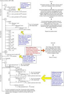
Figure (4) summarizes the overall flow of software. It shows tree structure of very important monitor_keypad() function. This function invokes many other functions depending on the pressed key and set or reset mode status flags. Strictly speaking this function does not execute any control operations; instead it transfers the control to main program to handle the important operations and thus indirectly executes it. For example if key ‘A’ is pressed then functions understands that fully automatic mode has to be executed. The monitor_keypad() function waits for the key ‘E’ is to be pressed and upon detecting the key press it initializes the operations related to fully automatic mode; it sets all related mode status flags and uploads to internal EEPROM; loads basic parameters from the external EEPROM to the RAM and transfers control to main() function. Main function performs operations as per status flag condition. Thus washing mode related operations are indirectly executed by ISR. But ‘On/Off’ and ‘S’-settings are directly executed by ISR. While setting the parameters as per user requirements, through keypad parameters are read and directly uploaded to predefined address locations. Delayed start option can be set to each semi automatic mode. One of the messages provides the option to enter the delay time. Default delay is zero. Since external RTC is used as time base, PIC timer modules can be efficiently used in programming. Any one of the timer interrupts can be used to read A/D module in regular interval of time, instead of reading in main() function. Results are stored in predefined variables. Drawback of this method of programming is that read value may not be ‘instantaneous’; it may be older by some microseconds or milliseconds.
The proposed design can be easily a part of home automation. The system is flexible and safer to use. Smart features can be added or withdrawn as per requirements and hence design is fully cost effective. The same design methodology adopted here can be extended to design the commercial product. If cost is not a criterion, then hardware can be easily modified to add an independent BLDC (or three phase) motor controller either through multiplexed serial port or by replacing GSM module by BLDC (three phase) motor controller.
For more detail: Embedded System for Automatic Washing Machine using Microchip PIC18F Series Microcontroller


