
Summary of dsPIC30F2012 breadboard
Bernard presents a dsPIC30F2012-based Arduino-like prototyping board, describing its features, capabilities, and development workflow. He outlines the microcontroller specs, compares higher-end dsPICs, discusses software tools (MPLAB, C30, MikroElektronika, HI-TECH, CCS), and explains programming options including ICSP and using an RS232 bootloader for in-circuit firmware updates.
Parts used in the dsPIC30F2012 breadboard:
- dsPIC30F2012 microcontroller
- Graphic LCD module (received from Hobby parts program)
- Pref board (protoboard)
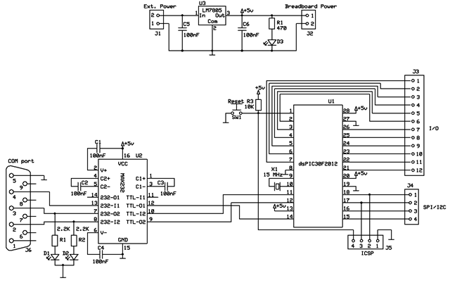
- RS232 interface circuitry
- ICSP connector
- Power supply components (for MCU and peripherals)
- Clock/PLL components (crystal or oscillator and capacitors)
- Passive components (resistors, capacitors)
- Headers and connectors for I/O
Bernard introduces us to the dsPIC microcontroller. He shows us his Arduino like project board for a dsPIC and gives advice on software development tools.
This article was submitted by Bernard Klinc as part of the “Hobby parts for articles” program. Bernard received a graphic LCD module for this great article. You may remember Bernard from his previous Accelerometer Based Mouse article and video.
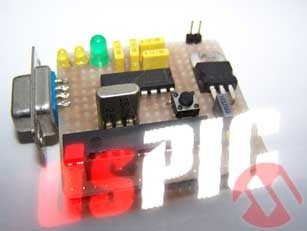
This thing may remind you of an Arduino but it’s not, it’s not even an AVR but a dsPIC30F2012. Lots of times I want to try out something, but I’m too lazy to make the whole thing over and over on a breadboard so why not solder it together quick on a pref board so I can just stick it in. And always too lazy to put on RS232, but it’s a great debug so that’s why it’s on the board, actually it’s the only feature that’s built in to the board, because its really the only thing I need.
And what can this dsPIC do? Well it has things like:
- 24KB of flash (CPU write access)
- 2KB of RAM
- 1KB of EEPROM
- 16 Bit 30MIPS CPU
- DSP Engine
- 8 channel 12bit ADC
- 2 PWM Outputs 16 bit
- 1 UART addressable
- 1 Serial (SPI/I2C) up to 30Mbit
- Clock PLL
This is not a high end dsPIC its just a small and easy one. The better ones have 256KB of flash and 16KB RAM, faster CPUs at 40MIPS, 32 ADC channels, 4 UART, 3 serial etc …
Anyway the bigger dsPICs are quite packed with features. So what can you make with such a MCU, well microchip has made voice recognition, 12 channel EQ and other neat stuff with them. But things like the voice recognition library is not free you need to buy it.
Speaking of software costs microchip makes a official compiler for them that works in there IDE called MPLAB which is free, but on its own it can only do assembler , but they also make a C compiler that also runs inside the IDE. There are 3 C compilers that is C18 (For the PIC18F family) C30 (For all 16 bit) and C32 (For the all new 32bit family). Also MPLAB includes a simulator for testing your code and supports debuggers, obviously only the official ones made by microchip.
You can get MPLAB and the C compiler from Microchips web site
Now you are probably wondering about the unofficial compilers so here are a few
- CCS C Compiler
- MikroElektronika C,Basic and Pascal Compilers
- HI-TECH C Compiler
So you are going to ask which is the best. Well cant really tell you since I only used MPLAB and MikroElektonikas compilers. What I can say about them is the Compilers from MikroE are very easy to use, great libraries and help, with lots of example code. But it seems a bit clumsy to me when trying to do something a bit more complicated. Still it’s a great compiler especially for beginners. The development boards from them are great, they will set you back around a 100 bucks. I used a lot MPLAB C30 for dsPICs and it runs pretty good, however it’s a more professional software so its everything but easy to use. It takes some time to figure it out but then its not a problem. Unlike MikroE compilers which you can get the hang of in like 10 minutes if you already know the basics of C, Basic or Pascal.
But when you have your program you need to get it in to the MCU. This board has a ICSP connector so it can be programmed by normal programmers. But you can take the advantage of the on board RS232 by using a boot-loader.
If you are not familiar with boot-loaders, this is how they work. Basically it’s a small program that runs when the PIC starts up and checks for a signal to go in to programming mode, if not then just let the program run that’s already in the memory. But if it gets a sign (a high on a pin, data in the port etc) then it will start communicating with the PC. Then the PC can send it the program and the boot-loader will write it in to the flash. After it’s done it just runs the program and after that the program has full control over the COM port.
You can get a boot-loader that works on PIC16F, PIC18F and dsPIC devices here.
For more detail: dsPIC30F2012 breadboard
- What microcontroller is used on the project board?
The dsPIC30F2012 microcontroller is used on the project board. - What built-in feature does the board include for debugging and programming?
The board includes an RS232 interface as the built-in feature for debugging and programming. - How much flash and RAM does the dsPIC30F2012 have?
It has 24KB of flash and 2KB of RAM. - Can the board be programmed without an external programmer?
Yes, it can use a boot-loader over the on-board RS232 to receive programs from a PC. - What official development environment and compiler does Microchip provide?
Microchip provides the MPLAB IDE and C compilers such as C30 for 16-bit devices. - Are there unofficial compilers available for dsPIC development?
Yes, unofficial compilers listed include CCS C Compiler, MikroElektronika compilers, and HI-TECH C Compiler. - What peripheral features does the dsPIC30F2012 include?
It includes an 8-channel 12-bit ADC, 2 16-bit PWM outputs, 1 UART, serial interfaces (SPI/I2C), DSP engine, and a clock PLL. - Is the dsPIC30F2012 a high-end dsPIC?
No, it is a smaller, simpler dsPIC; higher-end dsPICs have more flash, RAM, faster CPUs, and more peripherals. - What is a boot-loader and how does it work on this board?
A boot-loader is a small program that checks for a signal to enter programming mode at startup and, if triggered, communicates with the PC to receive and write firmware into flash via the RS232 interface.
