Summary of DIY LM1876 Dual 20W Audio Power Amplifier
This article details a DIY dual 20W audio power amplifier using the LM1876 IC. It features low distortion, operates on a symmetrical ±15VAC supply converted to ±21VDC, and includes standby functionality controlled by a potentiometer switch. The design incorporates noise reduction inductors, large smoothing capacitors, and a substantial heatsink for thermal management.
Parts used in the DIY LM1876 Dual 20W Audio Power Amplifier:
- LM1876 Integrated Circuit
- Transformer (±15 0 15 VAC or 0 15 30 VAC)
- Vishay KBU6M 6A 1000V Bridge Rectifier (BR1)
- Coilcraft MSS1260-332NL 3.3uH 5A Inductors (L1 and L2)
- 6800uF 50V Electrolytic Capacitors (C7 and C8)
- 100uF and 100nF Bypass Capacitors
- 3.5mm Stereo Socket
- Stereo Potentiometer with Switch
- RCA Connectors
- Heatsink
- D1 LED
We are building another enjoyable weekend DIY project. This is an audio power amplifier based on LM1876 which can deliver up to 20W per channel into 4 or 8 ohm load and guarantees less than 0.1% THD + N (Total Harmonic Distortion + Noise).
The amplifier is powered by -15 0 15 VAC symmetrical supply. The full bridge diode rectifier and the smoothing capacitors convert the AC input to ±21 VDC which is used to power LM1876. The inductors on the AC input line reduces the noise arising from the mains line.
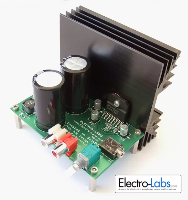
The audio input is connected to the board via 3.5mm stereo socket. The stereo potentiometer adjusts the amplitude of the audio signal. The potentiometer also includes a switch which pulls the Standby pins to logic high and makes the amplifiers go into the standby mode. In standby mode, LM1876 draws about 4.2mA and the power dissipation reduces significantly. The audio output of the amplifiers are connected to RCA connectors on the board.
LM1876 generates quite amount of heat so a heatsink is required to cool down the IC. A big heatsink is used for this purpose.
Circuit Design
The schematic of the project is drawn in SoloCapture, the schematic editor of SoloPCB tools. SoloCapture makes the schematic drawing process very easy and fast. You can download SoloPCB tools at Fabstream.com for FREE.
You can download the SoloPCB design files of the project by using the link below.
- How much power does this amplifier deliver?
The amplifier delivers up to 20W per channel into 4 or 8 ohm loads. - What is the total harmonic distortion of the circuit?
The project guarantees less than 0.1% THD + N. - Can I use a single supply instead of a symmetrical one?
A special single supply configuration exists but requires about 40VDC and causes performance degradation. - What component reduces noise from the mains line?
A pair of 3.3uH 5A inductors connected in series reduce power line noise. - How does the standby mode function work?
The potentiometer switch pulls the Standby pins to logic high to enter standby mode. - Does the amplifier draw significant power in standby mode?
In standby mode, the LM1876 draws about 4.2mA and significantly reduces power dissipation. - Why are resistors R7 and R8 included in the design?
They discharge the capacitors after power-down to prevent electrical shock. - Is a heatsink required for this project?
Yes, a big heatsink is required because the LM1876 generates quite an amount of heat. - Where should the bypass capacitors be placed?
The 100uF and 100nF bypass capacitors must be connected as close as possible to the VCC and VEE pins of the LM1876.