Disk Based Data Logger using PIC18F458 with Proteus Simulation

Summary of Disk Based Data Logger using PIC18F458 with Proteus Simulation


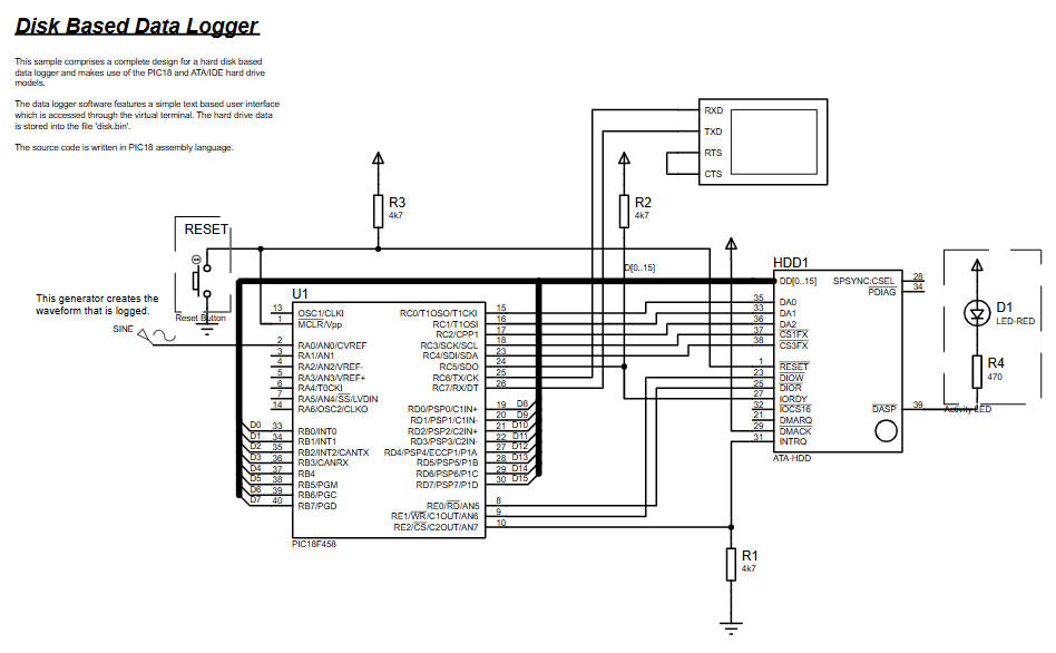
This project implements a disk-based data logger using a PIC18F458 microcontroller to sample ADC data and store it sector-by-sector on an ATA/IDE hard disk, controlled via an RS232 serial terminal and fully testable in Proteus VSM. It features interrupt-driven sampling, LBA sector writes/reads, assembly firmware modules for ATA driving, logging, and dump utilities, and is suitable for learning low-level disk interfacing and embedded data acquisition.

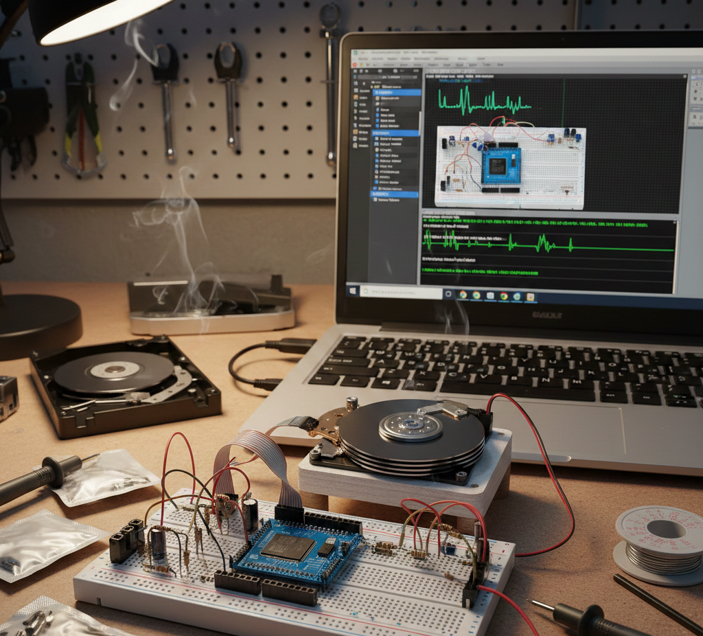
Parts used in the Disk Based Data Logger:

  • PIC18F458 Microcontroller
  • ATA/IDE Hard Disk Drive
  • RS232 Serial Interface (Virtual Terminal)
  • Resistors (pull-ups and LED current limiting)
  • Status LED
  • Reset Button

Introduction

This Disk Based Data Logger is a practical microcontroller project that demonstrates how a PIC18 microcontroller can directly interface with an ATA/IDE hard disk to record data. Designed and tested using Proteus simulation, the project showcases real-world embedded systems concepts such as low-level disk access, interrupt-driven data logging, and RS232 communication.
The system logs sampled data to a hard disk sector-by-sector and allows users to control and retrieve logged data through a serial terminal. It’s an excellent example of practical electronics combining firmware, hardware interfacing, and data storage.PIC18F458 Data Logger is a disk based embedded system designed to store analog data using an ATA hard disk with RS232 control and Proteus simulation support.

Embedded Disk Data Logger
Illustrative View of the Concept.

How the Project Works (Overview)

The PIC18F458 acts as the main controller, managing data acquisition, buffering, and storage. Data samples are collected using the ADC module, temporarily stored in RAM, and written to an ATA hard disk using standard IDE commands.
User interaction happens through an RS232 serial interface, allowing commands such as starting logging, stopping logging, and dumping stored data. Interrupts ensure accurate timing and efficient background logging while the main loop handles user commands.

Block Diagram / Workflow Explanation

  1. RS232 Interface
    The user sends commands via a serial terminal (help, start logging, dump data).

  2. Timer & ADC Triggering
    Timer0 periodically triggers ADC conversions using interrupts.

  3. Data Buffering
    ADC samples are stored in a RAM buffer until a full sector is ready.

  4. ATA Hard Disk Interface
    Buffered data is written to the hard disk using LBA addressing.

  5. Data Retrieval
    Stored sectors can be read back and displayed as hexadecimal values over RS232.

Key Features

  • Direct ATA/IDE hard disk interfacing without external controllers

  • Interrupt-driven ADC sampling for consistent data logging

  • Sector-based data storage using LBA addressing

  • RS232 command-line interface via virtual terminal

  • Complete Proteus VSM simulation support

  • Written entirely in PIC18 assembly language

Components Used

  • PIC18F458 Microcontroller

  • ATA/IDE Hard Disk Drive

  • RS232 Serial Interface (Virtual Terminal)

  • Resistors (pull-ups and LED current limiting)

  • Status LED

  • Reset Button

Applications

  • Embedded data logging systems

  • Sensor data recording and monitoring

  • Industrial data acquisition prototypes

  • Learning ATA/IDE protocol fundamentals

  • Advanced PIC microcontroller training projects

Explanation of Code (High-Level)

The firmware is structured into clear functional modules:

  • Initialization Routines
    Configure USART, ADC, timers, I/O ports, and reset logging pointers.

  • Command Handler
    Processes user input commands such as help, version, log, and dump.

  • Interrupt Handlers

    • High priority: Timer0 overflow triggering ADC conversions

    • Low priority: ADC completion and buffer management

  • ATA Driver Routines
    Handle register reads/writes, sector read/write operations, and LBA addressing.

  • Logging Engine
    Buffers ADC data and writes it to disk when a sector is full.

  • Dump Utility
    Reads logged sectors from disk and outputs data via serial in hex format.

Source Code

Download
; General temps
TMP1		equ	0x000000
TMP2		equ	0x000001

; Current LBA sector address for reading/wring
ATA_A0		equ	0x000002
ATA_A1		equ	0x000003
ATA_A2		equ	0x000004
ATA_A3		equ	0x000005

; Counter used to track data words read/written to/from ATA
ATA_CNT		equ	0x000006

; High priority interrupt temps
STATUS_TEMP_H	equ	0x000007
WREG_TEMP_H	equ	0x000008
BSR_TEMP_H	equ	0x000009

Proteus Simulation

In Proteus, the simulation accurately models the PIC18F458, ATA hard disk interface, and RS232 communication.
When the simulation runs:

  • A virtual terminal displays command prompts

  • Logging starts and stops via keyboard input

  • Disk sectors are written and read in real time

  • Data appears as hexadecimal output during dump operations

This makes it ideal for testing firmware logic without physical hardware.

(FAQs)

1. Can this project run entirely in Proteus simulation?

Yes, it is fully designed for Proteus VSM and works without physical hardware.

2. Why is an ATA hard disk used instead of EEPROM or SD card?

It demonstrates low-level disk control and sector-based data storage.

3. Can the logging interval be changed?

Yes, by modifying Timer0 settings and ADC trigger timing in firmware.

4. Is this compatible with other PIC18 microcontrollers?

Only devices with similar I/O and memory mapping would be suitable.

5. Why is assembly language used instead of C?

Assembly provides precise timing and full control over ATA signaling.

6. Can sensors be added to this project?

Yes, any analog sensor can be connected to the ADC input.

7. What baud rate does the serial interface use?

The firmware configures RS232 communication at 9600 baud.

8. How is data stored on the disk?

Data is written sequentially using Logical Block Addressing (LBA).

Conclusion

This Disk Based Data Logger using PIC18F458 is a powerful learning project that blends embedded systems, disk protocols, and real-time data acquisition. It offers hands-on insight into how microcontrollers interact with mass storage devices at a low level.
Perfect for advanced learners, this project builds strong fundamentals in firmware design, Proteus simulation, and hardware interfacing—all essential skills for modern embedded engineers.

Quick Solutions to Questions related to Disk Based Data Logger:

  • Can this project run entirely in Proteus simulation?
    Yes, it is fully designed for Proteus VSM and works without physical hardware.
  • Why is an ATA hard disk used instead of EEPROM or SD card?
    It demonstrates low-level disk control and sector-based data storage.
  • Can the logging interval be changed?
    Yes, by modifying Timer0 settings and ADC trigger timing in firmware.
  • Is this compatible with other PIC18 microcontrollers?
    Only devices with similar I/O and memory mapping would be suitable.
  • Why is assembly language used instead of C?
    Assembly provides precise timing and full control over ATA signaling.
  • Can sensors be added to this project?
    Yes, any analog sensor can be connected to the ADC input.
  • What baud rate does the serial interface use?
    The firmware configures RS232 communication at 9600 baud.
  • How is data stored on the disk?
    Data is written sequentially using Logical Block Addressing (LBA).

About The Author

Ibrar Ayyub

I am an experienced technical writer holding a Master's degree in computer science from BZU Multan, Pakistan University. With a background spanning various industries, particularly in home automation and engineering, I have honed my skills in crafting clear and concise content. Proficient in leveraging infographics and diagrams, I strive to simplify complex concepts for readers. My strength lies in thorough research and presenting information in a structured and logical format.

Follow Us:
LinkedinTwitter