Background
DDS stands for Direct-Digital Synthesis. This synthesizer is simply a circuit that can create a sine- wave signal from a reference crystal and a programable frequency-register. All this circuit needs is a reference oscillator (crystal) and some filter.
See fig above: A crystal oscillator (50MHz in my case) is connected to the input (Clock in) of the DDS.
The phase accumulator calculate the frequency you want the output to have. A sine memory map send data to the D/A and at the output you will have a sinus-signal with the desired (programmed) frequency.
You can program the output frequency from 0Hz to 50MHz, but according to the sampling theory (Shannon, Nyquist) practically, the output is limited to about 45% of the maximum clock rate at which the logic can be operated. This means that the sinus-output can reach from 0 Hz to about 25MHz with a 50MHz crystal. I think that is really good.
Inside the DDS is a programable divider wich divid the Clock in with 232 and multiply it with a programable register.

Example:
The highest resolution will therfore be: 50MHz / 232 => 0.011641532Hz.
This means that you can program the output from 0Hz to 25MHz with 0.011Hz step and have an almost perfect sinus output signal, WOW!
When can this be useful?
Lets say you want to build a 6M (50MHz) fine tuned receiver and maybe you want it to be a digital tuning. (See pic above). Now, the first mixer mix the input frequency with a crystall controlled frequency so from this mixer you will get an IF about 10MHz. Next mixer will mix the IF with the DDS frequency 0-20 MHz and the output is demodulated to an audio signal.
If you program the DDS so the output is almost 0 Hz you will receive at 40MHz and if you program the DDS so the output is 20MHz you will receive at 60MHz.
Conclusion: With the DDS you will now be able to tune the receiver from 40MHz to 60MHz. The smallest stepsize will be 0.011Hz. That is amazing!
The Registers in the DDS can be changed with a few micro seconds, so you can jump between different frequency really fast. Maybe you want to build a scanner wich scann really fast, the you should use a DDS. A PLL-synthesizer will never be as fast.
Maybe you want to build a sweep oscillator to tune your IF filter or crystal filter (0-25MHz), then a DDS is perfect for you. You can also use the DDS to build a programable low frequency tone generator.
My next DDS project will be a police scanner that scann from 79 to 81 MHz. It is only a few MHz and a DDS will really make it fast scanning. The nice with that project is that I dont need to find an exact 69MHz crystal for the first mixer since I can program the DDS.
Now I have introduced you to DDS tecnology. If you want to know all the details you should go to this page : ddstutor.
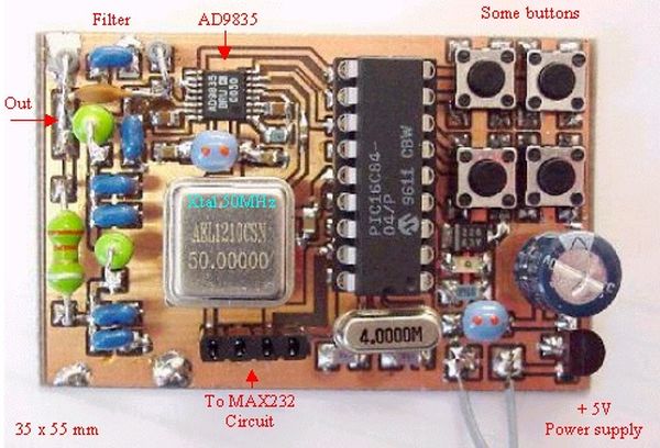
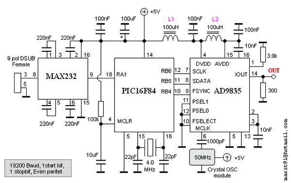
I will now go on explain how you can build a controller for the DDS circuit AD9835. I will also explain the internal register and at the bottom You will be able to dowload some software to this project.
Internal Registers
I will now explain the internal registers and don’t worry if you wont understand right away. You really don’t need to understand all the registers and bits to be able to use my DDS construction. I will later show how you can connect a PIC between a computer and the DDS. I have implemented everyting into a PIC, so you only need to know how to handle RS232 on your computer to be able to set the desired frequency from the DDS. If you know how to program a PIC you won’t have any problem to set the registers yourself. A good help is to download the datasheet and read more about the details.
The pic above shows the internal block in the chip. Lets start with the yellow part.
There are two 32 bits registers wich can set the divider ration FREQ 0 REG and FREQ 1 REG. You can choose wich register you want to be present for the phase accumulator by the register SELSRC (Select Source Bit). IF SELSRC is = 0 the selection of register is made by the FSELECT pin on the AD9835. IF SELSRC is = 1 the selection of register is made by the bit (internal register).
In most cases one only need 1 register, so I have choose to set the SELSRC = 0 and I choose to use FREQ 0 REG by conect the FSELECT pin to GND.
The blue part shows the phase register. There is 4 different registers wich all contains the phase of the signal. These register can also be selected by two pin on the ic or by two registers.
IF SELSRC is = 0 the selection of the phase registers are made by the PSEL 0 and PSEL 1 pins on the AD9835. IF SELSRC is = 1 the selection of the phase register is made by the bit (internal register).
I never need to change the phase, so I have set the SELSRC = 0 and conected the pins PSEL 0 and PSEL 1 to GND.
For futher data see the datasheets.
The green part is the hart of the DDS. It is here the sinus signal is built up.
The purple part is the controlling unit. FSYNC, SCLK and SDATA are for setting the registers.
FSYNC must go low to send data to the DDS. SCLK clocks data into the DDS and the SDATA is the data to the DDS.
For more detail: Direct Digital Synthesis (DDS) using PIC16F84 microcontroller

