Summary of Digital Thermometer using LM35 and PIC Microcontroller
This tutorial shows how to build a digital thermometer using a PIC16F877A microcontroller and an LM35 temperature sensor, reading analog voltage via the PIC's 10-bit SAR ADC, converting it to temperature, and displaying it on a 16x2 LCD. It includes component list, ADC explanation, conversion math, LCD interfacing code, and full C source for PIC with configuration bits and ADC/LCD routines. The circuit is powered by a 12V adapter and uses a 7805 regulator for 5V supply.
Parts used in the Digital Thermometer:
- PicKit 3
- LM35 Temperature Sensor
- 16x2 LCD
- PIC16F877A IC
- 40-pin IC holder
- Perf board
- 20 MHz Crystal oscillator
- Female and male Bergstick pins
- 33 pF capacitor (2 nos)
- 100 µF capacitor
- 10 µF capacitor
- 680 ohm resistor
- 220 ohm resistor
- 10K resistor
- 560 ohm resistor
- 10K potentiometer
- LED (any color)
- Soldering kit
- IC 7805 voltage regulator
- 12V adapter
- Connecting wires
- Breadboard
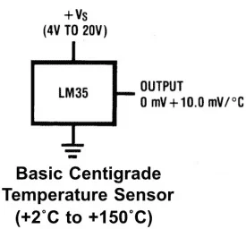
In this tutorial, we are making a Digital Thermometer using PIC microcontroller and LM35 Temperature Sensor. In this project, we will sense the temperature using LM35 and display it on 16×2 LCD. LM35 Temperature Sensor is accurate and cheaper and doesn’t require any external calibration. The output voltage is proportional to Celsius temperature scale and changes by 10mV per °C.

Material Required
- PicKit 3
- LM35 Temperature Sensor
- 16*2 LCD
- PIC16F877A IC
- 40 – Pin IC holder
- Perf board
- 20 MHz Crystal OSC
- Female and Male Bergstick pins
- 33pf Capacitor – 2Nos, 100uf and 10uf cap.
- 680 ohm, 220 ohm, 10K and 560ohm Resistor
- Potentiometer 10k
- LED of any color
- 1 Soldering kit
- IC 7805
- 12V Adapter
- Connecting wires
- Breadboard
LM35 Temperature Sensor:
LM35 temperature sensor has zero offset voltage, which means at 0°C the output will be 0V. The maximum voltage it can handle is 1.5V which means it can be able to sense a maximum temperature of 150°C (1.5V / 10mV).
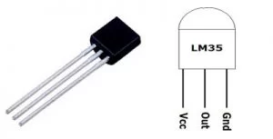
| Pin No | Function | Name |
| 1 | Supply voltage; 5V (+35V to -2V) | Vcc |
| 2 | Output voltage (+6V to -1V) | Output |
| 3 | Ground (0V) | Ground |
As we already told that LM35 gives analog output, so first we need to read that analog values using PIC Microcontroller and then we will convert them into digital values using ADC (Analog to Digital Conversion). So we will learn ADC in PIC Microcontroller before going any further.
ADC in PIC Microcontroller PIC16F877A:
There are many types of ADC available and each one has its own speed and resolution. The most common types of ADCs are flash, successive approximation, and sigma-delta. The type of ADC used in PIC16F877A is called as the Successive approximation ADC or SAR in short. So let’s learn a bit about SAR ADC before we start using it.
Successive Approximation ADC: The SAR ADC works with the help of a comparator and some logic conversations. This type of ADC uses a reference voltage (which is variable) and compares the input voltage with the reference voltage using a comparator and difference, which will be a digital output, is saved from the Most significant bit (MSB). The speed of the comparison depends on the Clock frequency (Fosc) on which the PIC is operating.
Now that we know some basics on ADC, lets open our datasheet and learn how to use the ADC on our PIC16F877A MCU. The PIC we are using has 10-bit 8-channel ADC. This means the output value of our ADC will be 0-1024 (2^10) and there are 8 pins (channels) on our MCU which can read analog voltage. The value 1024 is obtained by 2^10 since our ADC is 10 bit. The eight pins which can read the analog voltage are mentioned in the datasheet. Lets look at the picture below.
The analog channels AN0 to AN7 are highlighted for you. Only these pins will be able to read analog voltage. So before reading an input voltage we have to specify in our code which channel has to be used to read the input voltage. In this tutorial we will use channel 4 with a potentiometer to read the analog voltage at this channel.
The A/D module has four registers which has to be configured to read data from the Input pins. These registers are:
• A/D Result High Register (ADRESH)
• A/D Result Low Register (ADRESL)
• A/D Control Register 0 (ADCON0)
• A/D Control Register 1 (ADCON1)
Code and Explanation
The complete code for this Digital Thermometer using LM35 and PIC microcontroller is given at the end. The code is self-explained with comment lines and just involves the concept of interfacing a LCD with PIC Microcontroller and Using ADC module in PIC Microcontroller which we have already covered in our previous tutorials of learning PIC Microcontrollers.
Here we are just showing the calculations done for reading the analog output voltage from LM35 and then converting it into temperature values. So here we are converting the ADC value from LM35 into the voltage and then voltage value into temperature. Therefore, after getting the value we have seperated every character for displaying on LCD.
        adc = (ADC_Read(4)); // Reading ADC values
        volt = adc*4.88281; // Convert it into the voltage
        temp=volt/10.0;  // Getting the temperature values
        temp1 = temp*100;
        c1 = (temp1/1000)%10;
        c2 = (temp1/100)%10;
        c3 = (temp1/10)%10;
        c4 = (temp1/1)%10;
Now in the below code, set the LCD cursor and then print the output value
        Lcd_Clear();
        Lcd_Set_Cursor(1,3);
        Lcd_Print_String("Temperature");
        Lcd_Set_Cursor(2,5);
        Lcd_Print_Char(c1+'0');
        Lcd_Print_Char(c2+'0');
        Lcd_Print_String(".");
        Lcd_Print_Char(c3+'0');
        Lcd_Print_Char(c4+'0');
        Lcd_Print_Char(0xDF);
        Lcd_Print_String("C");
        __delay_ms(3000);
Working of Digital Thermometer
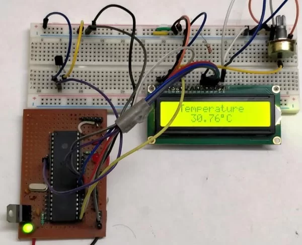
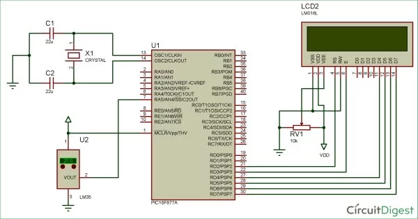
After uploading the code in the PIC micro-controller, power up the circuit using 12v adapter. The analog output of LM35 temperature sensor is fed to the analog input channel of the PIC controller. As the temperature increase the ADC value will also increase. That ADC value is further converted into voltage by multiplying it with 4.88281. Then the voltage value is converted to corresponding character for displaying it into 16*2 LCD.
#define _XTAL_FREQ 20000000
#define RS RD2
#define EN RD3
#define D4 RD4
#define D5 RD5
#define D6 RD6
#define D7 RD7
#include <xc.h>
#pragma config FOSC = HS // Oscillator Selection bits (HS oscillator)
#pragma config WDTE = OFF // Watchdog Timer Enable bit (WDT disabled)
#pragma config PWRTE = ON // Power-up Timer Enable bit (PWRT enabled)
#pragma config BOREN = ON // Brown-out Reset Enable bit (BOR enabled)
#pragma config LVP = OFF // Low-Voltage (Single-Supply) In-Circuit Serial Programming Enable bit (RB3 is digital I/O, HV on MCLR must be used for programming)
#pragma config CPD = OFF // Data EEPROM Memory Code Protection bit (Data EEPROM code protection off)
#pragma config WRT = OFF // Flash Program Memory Write Enable bits (Write protection off; all program memory may be written to by EECON control)
#pragma config CP = OFF // Flash Program Memory Code Protection bit (Code protection off)
void ADC_Initialize()
{
ADCON0 = 0b01000001; //ADC ON and Fosc/16 is selected
ADCON1 = 0b11000000; // Internal reference voltage is selected
}
unsigned int ADC_Read(unsigned char channel)
{
ADCON0 &= 0x11000101; //Clearing the Channel Selection Bits
ADCON0 |= channel<<3; //Setting the required Bits
__delay_ms(2); //Acquisition time to charge hold capacitor
GO_nDONE = 1; //Initializes A/D Conversion
while(GO_nDONE); //Wait for A/D Conversion to complete
return ((ADRESH<<8)+ADRESL); //Returns Result
}
//LCD Functions Developed by Circuit Digest.
void Lcd_SetBit(char data_bit) //Based on the Hex value Set the Bits of the Data Lines
{
if(data_bit& 1)
D4 = 1;
else
D4 = 0;
if(data_bit& 2)
D5 = 1;
else
D5 = 0;
if(data_bit& 4)
D6 = 1;
else
D6 = 0;
if(data_bit& 8)
D7 = 1;
else
D7 = 0;
}
void Lcd_Cmd(char a)
{
RS = 0;
Lcd_SetBit(a); //Incoming Hex value
EN = 1;
__delay_ms(4);
EN = 0;
}
Lcd_Clear()
{
Lcd_Cmd(0); //Clear the LCD
Lcd_Cmd(1); //Move the curser to first position
}
void Lcd_Set_Cursor(char a, char b)
{
char temp,z,y;
if(a== 1)
{
temp = 0x80 + b – 1; //80H is used to move the curser
z = temp>>4; //Lower 8-bits
y = temp & 0x0F; //Upper 8-bits
Lcd_Cmd(z); //Set Row
Lcd_Cmd(y); //Set Column
}
else if(a== 2)
{
temp = 0xC0 + b – 1;
z = temp>>4; //Lower 8-bits
y = temp & 0x0F; //Upper 8-bits
Lcd_Cmd(z); //Set Row
Lcd_Cmd(y); //Set Column
}
}
void Lcd_Start()
{
Lcd_SetBit(0x00);
for(int i=1065244; i<=0; i–) NOP();
Lcd_Cmd(0x03);
__delay_ms(5);
Lcd_Cmd(0x03);
__delay_ms(11);
Lcd_Cmd(0x03);
Lcd_Cmd(0x02); //02H is used for Return home -> Clears the RAM and initializes the LCD
Lcd_Cmd(0x02); //02H is used for Return home -> Clears the RAM and initializes the LCD
Lcd_Cmd(0x08); //Select Row 1
Lcd_Cmd(0x00); //Clear Row 1 Display
Lcd_Cmd(0x0C); //Select Row 2
Lcd_Cmd(0x00); //Clear Row 2 Display
Lcd_Cmd(0x06);
}
void Lcd_Print_Char(char data) //Send 8-bits through 4-bit mode
{
char Lower_Nibble,Upper_Nibble;
Lower_Nibble = data&0x0F;
Upper_Nibble = data&0xF0;
RS = 1; // => RS = 1
Lcd_SetBit(Upper_Nibble>>4); //Send upper half by shifting by 4
EN = 1;
for(int i=2130483; i<=0; i–) NOP();
EN = 0;
Lcd_SetBit(Lower_Nibble); //Send Lower half
EN = 1;
for(int i=2130483; i<=0; i–) NOP();
EN = 0;
}
void Lcd_Print_String(char *a)
{
int i;
for(i=0;a[i]!=’\0′;i++)
Lcd_Print_Char(a[i]); //Split the string using pointers and call the Char function
}
int main()
{
float adc;
float volt, temp;
int c1, c2, c3, c4, temp1;
ADC_Initialize();
unsigned int a;
TRISD = 0x00;
Lcd_Start();
while(1)
{
adc = (ADC_Read(4)); // Reading ADC values
volt = adc*4.88281; // Convert it into the voltage
temp=volt/10.0; // Getting the temperature values
temp1 = temp*100;
c1 = (temp1/1000)%10;
c2 = (temp1/100)%10;
c3 = (temp1/10)%10;
c4 = (temp1/1)%10;
Lcd_Clear();
Lcd_Set_Cursor(1,3);
Lcd_Print_String(“Temperature”);
Lcd_Set_Cursor(2,5);
Lcd_Print_Char(c1+’0′);
Lcd_Print_Char(c2+’0′);
Lcd_Print_String(“.”);
Lcd_Print_Char(c3+’0′);
Lcd_Print_Char(c4+’0′);
Lcd_Print_Char(0xDF);
Lcd_Print_String(“C”);
__delay_ms(3000);
}
return 0;
}
Read more detail:Digital Thermometer using LM35 and PIC Microcontroller
- What sensor is used to sense temperature in the project?
The project uses the LM35 temperature sensor. - Which microcontroller is used for the digital thermometer?
The project uses the PIC16F877A microcontroller. - How is the LM35 analog output read by the microcontroller?
The LM35 analog output is read using the PIC16F877A ADC module on an analog channel (ANx), specifically channel 4 in this tutorial. - What ADC resolution does PIC16F877A provide?
The PIC16F877A provides a 10-bit ADC giving values from 0 to 1024. - How is ADC value converted to voltage and temperature in the code?
The code multiplies ADC value by 4.88281 to get voltage, then divides by 10.0 to obtain temperature in Celsius. - Where is the temperature displayed?
The temperature is displayed on a 16x2 LCD. - What supply is used to power the circuit?
The circuit is powered by a 12V adapter with a 7805 regulator to provide 5V. - Does LM35 require external calibration according to the article?
No, the article states LM35 is accurate, cheaper, and does not require external calibration. - What change in LM35 output corresponds to 1°C?
The LM35 output changes by 10 mV per degree Celsius. - Which LCD interface mode and pins are used in the code?
The code uses 4-bit LCD mode with RD2 as RS, RD3 as EN, and RD4–RD7 as data lines D4–D7.