Summary of Digital stopwatch using microcontroller
This article describes building a digital stopwatch using a PIC16F73 microcontroller, simulated in Proteus 7 and coded with mikroC Pro. The stopwatch uses a 16x2 LCD and three push buttons (Start, Pause, Stop) with a 20 MHz crystal; connections and a compiled HEX file are provided so users can load the microcontroller, power the board, and operate the stopwatch. The project is simple, modifiable, and supported by the author for troubleshooting.
Parts used in the Digital stopwatch project:
- PIC16F73 (1 pc)
- 16x2 LCD (1 pc)
- Push Button (3 pcs)
- 20 MHz Oscillator / Crystal (1 pc)
- 5V Power Supply / VCC (wiring)
- Ground connection
How much time this event will take to finish?OK, Let’s countdown the time.So a stopwatch is the best solution.Just press the start button to start countdown then stop when the event completed.Now every cellphone has this feature but i was determined to make a digital stopwatch using micro controller as I am very fond of this type of works.
This project is about to make a digital stopwatch. Whole project is simulated in Proteus 7.
MikroC is used to write the code.
This project is about to make a digital stopwatch. Whole project is simulated in Proteus 7.
MikroC is used to write the code.
The circuit is easy and we just need
- PIC16F73(1pc)
- 16×2 LCD(1pc)
- Push Button(3pc)
- 20 MHZ Oscillator(1pc)
Here we use three buttons.
- START Button
- PAUSE Button
- STOP Button
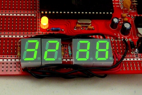
To understand the whole project look at the final output of the project.
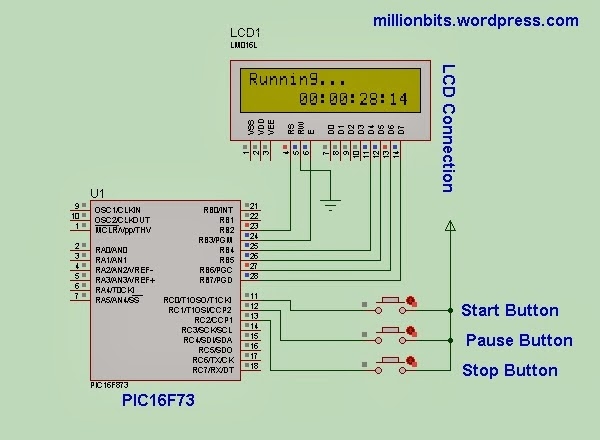
Just make the connections as the figure shown.
This project file is compiled in MikroC Pro 5.8.0.
Connection Detail:
- PIC RB2 —- LCD RS
- PIC RB3 —- LCD EN
- PIC RB4—- LCD D4
- PIC RB5—-LCD D5
- PIC RB6—-LCD D6
- PIC RB7—-LCD D7
- GROUND—-LCD R/W
- PIC RC0—-START BUTTON
- PIC RC1—-PAUSE BUTTON
- PIC RC2—-STOP BUTTON
- 20 MHZ OSCILLATOR IN XTAL PINS
- PIC VCC 5V
 Load the HEX file to the pic microcontroller.
Give power to the board and press the buttons to see the output in LCD.
Any Complexity ? Or Facing Problem ?? Just put comment. I shall try to help.
As I have shared the whole project code you can modify the code in MikroC as you need.
For more detail: Digital stopwatch using microcontroller
- How long will the event take to finish?
The article does not specify a preset event duration; the stopwatch runs until you press the stop button. - Can I start and stop the stopwatch with buttons?
Yes, three push buttons are used for Start, Pause, and Stop functions. - Does the project require a specific microcontroller?
Yes, the project uses the PIC16F73 microcontroller. - What software was used to write the code?
The code is written in mikroC Pro (compiled in mikroC Pro 5.8.0). - Can I simulate the project before hardware implementation?
Yes, the whole project is simulated in Proteus 7. - How is the LCD connected to the PIC?
The LCD uses RB2 for RS, RB3 for EN, and RB4–RB7 for D4–D7; R/W is grounded. - What clock source is used for the PIC?
A 20 MHz crystal oscillator is connected to the PIC XTAL pins. - How do I load the program onto the PIC?
Load the provided HEX file into the PIC microcontroller. - What power supply is required?
The PIC VCC should be connected to 5V and ground provided. - Can I modify the code?
Yes, the full project code is shared and can be modified in mikroC.