Adding a Digital Meter and Functions to Analog Geiger Counters
The Digital Meter Adapter is a expansion module for adding digital functions to Analog Geiger Counters that have a pulse output. If you’re geiger counter outputs a ttl pulse for every radioactive particle it detects, your Geiger counter will connect to Images SI Inc.’s DMAD Digital Meter Adapter.
The DMAD has three functionalities to enhance the capabilities of Analog Geiger Counters. It counts pulse from analog geiger counter and convert reading into radiation level. Both count data and radiation level is displayed on the LCD display. Has a serial output that is compatible with Images USB-TTL cable interface. The serial output and USB cable may be used with Images SI Inc.’s free radiation monitoring and graphing software. Another function of the DMAD is a true Random Number Generator.
Images Radiation Monitoring and Graphing program shown below is compatible with the DMAD when used in conjuction our USB-TTL Cable adapter and suitable analog Geiger counter.
The DMAD Adapter
The DMAD is an expansion module that adds three functions – Digital Meter, Serial interface and Random Number Generator. It provides a single module solution for adding various extra features to enhance capabilities of analog Geiger Counters. The DMAD connects to an Analog Geiger counter using a 3.5 mm plug. This plug can be connected to the digital output or headphone jack of most Analog Geiger counters. This connection expects to see a +5V TTL pulse every time the Geiger counter detects a radioactive particle.
Functionality is selected by a switch located on backside B7.
Digital Meter Function:
Digital Meter provides the count in either CPS (Counts per Second) or CPM (Counts Per Minute) on the top line of the LCD display. The bottom line of the LCD display provides the approximate radiation level.
B7 Switch/Up Position = Digital Meter and RS-232:
When B7 is not set (switch in up position, open), module will function as Digital Meter. The
B7 switch is checked for position when module is turned on, so switch setting should be changed
only when module is off. Changing the switch setting while module is powered will not change
functionality of module.
Usage
Switch B7 In up position (Unset) selects Digital Meter mode with RS232 (serial) output mode
In this mode, module has four options that may be selected using the switches on the back of
the circuit.
Switch B6 sets whether the output radiation level is given in conventional
terms mR/hr (milliRads/milliRem per hour) or System International (SI) mSv/hr
(milliSiverts per hour).
Switch B4 sets the timing mode of either one minute or one second. When B4 is set to oneminute
mode, the radiation level is given in μR/hr or μSv/hr. This mode is convenient for
checking the local background radiation.
Irrespective of the selection of CPS/CPM, CPS data will be sent out serially every second,
which can be interfaced with PC for Graphing & Charting Purpose. The RS232 interface adaptor
sends the counts per second information transmitted in two bytes. A high byte, that is multiplied
by 256 and added to the low byte for the total count.
Geiger Counter Graphing & Logging Software
Geiger Counter measurements can be used for Graphing & Logging purposes by connecting
Analog Geiger Counter to PC via this module, using various PC Softwares. Two such softwares
are available on Images SI website.
Geiger Counter Charting Software is proprietary of Images SI, and is available free of charge http://www.imagesco.com/catalog/geiger/counter_accessories.html.
Geiger Counter Charting Software runs on Windows. Download the software installation file from Images SI website & install it on your PC. Connect the module to PC’s serial port via USB-TTL Cable adaptor. Module should be set to operate in DMAD / RS232 interface mode by setting switch B7 Up.
Make sure the program’s COM port is set to the correct COM port of the USB-TTL cable driver. Both the program and USB cabler counter COM ports must be the same for the program to begin graphing. The graphs generated by the program may be saved to disk and loaded for viewing and analysis later on. See screen image above.
Random Number Generator Function
B7 Switch Set = Random Number Generator:
When B7 switch is in its Down position it is set and the module will function as Random Number Generator. Switch B7 is only checked when module is turned on, so switch setting should be changed only when module is off. Changing the switch set-ting while module is pow-ered will not change func-tionality of module.
Random Number Generator functionality generates Random Numbers true in nature. For this purpose, the module can be used with either of Analog or Digital Geiger Counters. The module plugs into Digital out or Headphone jack as before. Range of random number generated is selected by combination of switch settings B6, B5, B4.
The serial output transmitts the random number generated. The information is transmitted as a single bytes. This data may used by various PC programs that require true random numbers.
Writing Your Own Software to Communicate with the Adapter
You can write your own software to communicate with this module. Serial data is sent out as a two byte number (most significant byte first) with the following specifications: 9600 Baud, Inverted, 8 data bits, no parity and one stop bit.
Construction Of DMAD Module
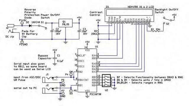
Figure 1 below shows the schematics of DMAD Geiger counter expansion module.
he circuit uses a pre-programmed 16F88 microcontroller and a standard 16 x 2 LCD display. Module derives itspower from either an 9V external battery, or optional 6VDC power supply. Power is regulated on board to 5V. Input to module comes via 3.5 mm jack J1. Module features TTL serial out port via a two pin header or 3.5 mm jack J2. Either of which can be used for an interface. The 3.5mm jack is used with USB-TTL serial cable. The back of Universal Expansion Module has a Power switch, LCD backlight switch, Contrast control, Selection switches.
Begin by mounting and soldering the 16-pin header on the bottom of the board (the side with no silkscreen) as shown above in figure 2. Next, on the top of the board (silkscreen side), mount and solder the ICS-16 for the PIC16F88 microcontroller to the board, making sure the notch on the socket is aligned with the silkscreen. Now, mount and solder the two slide switches marked S1 & S2, followed by power jack P3. Next, mount and solder R1 the 33 ohm resistor. Next mount the 1N5817 diode D2 making sure to align the stripe on the diode with the strip on the silkscreen. Q1 is the regulator. When mounting the regulator, be sure the flat side is oriented with the flat side of the silkscreen. Next mount the three 2-pin headers in the top two sets of holes marked P1,P2 then P4,P6 and P5,P7. These 2-pin headers provide an alternate method of connecting to the board to supply power, digital input, and serial output respectively.Now, mount C1, the 0.1uf capacitor and the two 10uf capacitors marked C2 & C3. When mounting these capacitors be sure the longer lead is oriented to the hole marked positive.
Mount and solder the Digital Input jack J1 and serial Output jack J2. Followed by the 20K pot in the spot marked R2, Contrast Control. Mount and solder the 4-position switch in U2. Next, mount and solder 18 Pin socket U1 to the PC board.
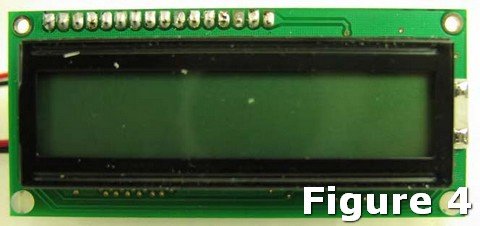
Next mount and solder the LCD module to the 16-pin header. Figure 4 is a photo of the top of the completed circuit.
RS-232 Adapter for used with older PC’s with a serial DB-9 Connector:
Begin with wiring the 3.5mm jack. The shorter lead inside the jack is the positive, the longer is the negative (ground). To the positive (tip) terminal solder a red wire, to the ground solder a black wire (See Figure 5 & 6). Once the wires are soldered to the plug, thread the wires through the body of the jack and screw the body down on the plug.
To utilize the RS-232 you need to connect a DB9 connector to the wires off the 3.5mm (1/8”) jack. The DB-9 female connector is wired as shown in figures 7 and 8. Once the internal DB9 connections are soldered.
Soldered the red wire from the jack to the I/O line of the DB9 connector. Don’t forget to wire in the 1K resistor. Next the and ground wires from the DB9 connector and 3.5 mm plug are connected together Encase DB-9 connector in DB-9 connector hood.
If you chose to fabricate the RS-232 cable it will look like the illustration.
To use this cable plug the 3.5 mm (1/8”) jack into the serial out socket (J2),
Connect the DB9 connector to an open RS-232 port (COM port) on your computer.
Alternatively use can also use a USB port, by connecting a USB-TTL Serial cable to module’s serial port output to an open USB port of your computer.
Either option provides a serial link interfaced with PC for Graphing & Logging Radiation Levels using Images SI Graphing Software available for free download on Images SI website.
RS-232 / Serial Functionality:
When in Digital Meter Mode the Serial output sends the Count Per Second, (CPS) detected by the Geiger counter to the PC. This is used to connect to the PC windows program. The count consists of two bytes, a high byte multiplied by 256 that is added to the low byte for the total count.
When in Random Number Generator Mode, the serial output sends the random number generated out to the PC. This is a one-byte number, whose range is determined by the jumpers B4 to B6.
USAGE
Set the switches for the units/time you want. Plug the 3.5mm (1/8”) jack into the Digital out of the Analog Geiger counter, and the opposite end of the cable into the J1 jack on the DMAD board.
For more detail: Digital Meter Adapter – DMAD