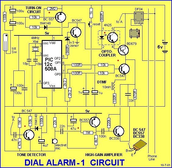
This is the lowest cost dialing alarm on the market and shows what can be done with an 8-pin microcontroller. The complete circuit is shown below. You cannot see all the features of this project by looking at the circuit – most of them are contained in the program. So, read on and see what we have included. . .
Dial Alarm-1 has a single input (although a number of sensors can be placed in parallel on the same input line). The circuit requires a trigger pulse to turn on a BC 557 transistor. This delivers power to the microcontroller. The micro starts to execute the program and outputs a high on GP2 to keep the “turn-on” circuit active. It also turns on the LED in the opto-coupler and this causes the line to be “picked up” via a high-gain Darlington transistor. The micro then dials two phone numbers and executes a series of events to alert the called party of an intrusion. The circuit also has a sensitive microphone with a high-gain amplifier. This is connected to the phone line when the alarm is triggered.
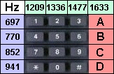
When the first number is dialled, a Hee Haw signal is sent down the line to alert the listener of an intrusion in the “target” area. Amplified audio of the room is then passed down the line. This signal is clear enough to detect conversations and/or movement in the target area and the listener can determine the situation. A second number is then called and the process is repeated. The two numbers are then called again and the alarm closes down. Simple but brilliant.
 Use Dial Alarm-1 as a “Back-Up” Alarm
This alarm has been developed in response to a number of recent large robberies reported in the news. Robberies are a constantly increasing crime, but very few are reported, unless they have a “twist.” Recently, the robbers navigated the conventional alarm system and broke into the night safe in the Manager’s office. The haul was quite significant and it’s surprising such a large amount of cash was kept on the premises. The weakest link in most alarm systems are the PIR detectors, used to detect movement. It’s a known fact that they are very easy to foil. It’s so easy we are forbidden to print details of how to do it. But many thieves must be aware of the trick and that’s why a back-up system is essential.
The cheapest back-up system is the use of the phone line. I know what you are going to say. Cutting the telephone line is an easy matter and offers little security. But finding the line in a premises is
not very easy and if there are two or more incoming lines, it’s difficult to know which is connected to the dialler. Nothing is infallible, but for a lot less than $50 you can build this project and have a back-up to protect your property.
The other advantage of our design is the “set and forget feature.” The alarm is designed to ring your mobile and if you keep your phone beside you 24 hours a day, you can have this peace of mind, whether you are in your office, factory, holiday house or quietly dining at your favourite restaurant.
You can protect any area where a telephone line can be installed. This includes houses-under- construction and outlying sheds.
Talking Electronics has been producing security devices for more than 15 years and this project is a culmination of those years of experience.
The high-sensitivity amplifier is our development and comes from our highly successful Infinity Bug. This device connects to the phone line anywhere in the world and when the number is rung, the infinity
bug answers the call and lets you listen in to the activities in the room. It’s just like being there. We have used the same circuit in this project. When it is activated, you can easily work out if it has been triggered by staff, a family member or an intruder. At least it prevents 90% of false alarms and offers enormous peace of mind.
The secret lies in the placement of the triggering device. We have provided only one input (trigger input). And there’s a reason for this. The idea is to place the sensor near the target area or on an actual device, near the microphone.
For instance, it you are protecting a house, a thief always goes to the main bedroom and rummages through the drawers and cupboards. In this case a drawer that is never used should be wired with a magnetic switch (reed switch) or a movement detector such as a mercury switch. These switches can be housed in a plastic case for easy screwing to a wall or door and are very reliable in operation. When the drawer is pulled out or the door opened, the switch is activated. If you are protecting a wall safe, the switch is placed near the safe in a clipboard or picture so that when the board or picture is moved, the alarm is activated. If a room is to be monitored, the switch is placed on the door so that when it is opened, the alarm is activated. If other valuables are being protected (such as a VCR, scanner etc) a suggestion is to place a clipboard against the item. The idea is the clipboard has to be moved to get at the “valuables.” The clipboard contains a magnet and the switch is nearby. The clipboard keeps the switch open (or closed) and when it is moved, the alarm is activated.
The ideal arrangement is to avoid touching the clipboard, drawer, door or other “prop” during normal activities and this keeps the alarm activated at all times.
Another suitable trigger device is a pressure mat. This is something that can be avoided by “those in the know” and you can monitor an area during your absence. The alarm can be used for other things too. You can determine when your business premises are opened up in the morning by placing a pressure mat or reed switch on a door. The same can apply to a particular room in your establishment.
The purpose of this article is not only to produce the worlds smallest dialling alarm but also show you how the program runs so you can modify any of the routines to suit your own particular requirements.
The program can be re-written to dial only one number for two rings then hang up, or three rings, then again after 2 minutes or any combination to suit your requirements. Many mobile phones identify the caller on the display and you can keep track of the exact time of arrival and departure of different personnel.
The alarm can be programmed to monitor machinery and dial your mobile when a breakdown occurs. It can monitor water level or even your mail box. The possibilities are unlimited and it’s just a matter of modifying the program to suit your own needs.
But before you change any of the program you have to understand what the program does and be capable of changing the instructions without upsetting the operation of the alarm.
Remember: A little knowledge is a dangerous thing. Before doing any re-writing of the program you need to read our notes on programming and carry out one small modification at a time.
This is really a very advanced project. The fact that is looks simple is the power of the microcontroller. It’s taking the place of at least 10 chips in a normal alarm.
Timing, tones and tunes have all been converted to instructions of a program. And the advantage of a program is the simplicity of alteration. A time-interval can be changed or a phone number altered with a few lines of code. Even new features can be added without the need for additional hardware. This project uses the ‘508A to its maximum and shows what can be done with an 8-pin microcontroller. Before we go any further we must state that this project cannot be connected to the public telephone system. Only approved devices can be connected to the Public Phone System and any experimental device must be approved for experimentation and connected via a “telephone Line Separating Device.” These are available from Altronic Imports for approx $100.
This is unfortunately the case and when we discuss connecting the project “to the line,” we are referring to an experimental telephone system such as the one we have put together at Talking Electronics, to test and develop projects such as these.
See the section “Testing The Project” on Page 2 for more details of the Test Circuit. It consists of 27v derived from 9v batteries, a 12v relay, a telephone and a socket, all in series. The 12v relay is included to limit the current.
THE CIRCUIT
The circuit consists of 6 building blocks.
1. The turn-on circuit. Click HERE to see the circuit working (or click the red dot in the circuit above).
2. The tone detector. Click HERE to see the circuit working. ( ” ” ” )
3. The DTMF wave-shaping circuit. Click HERE to see the circuit working. ( ” ” ” )
4. The high-gain audio amplifier. Click HERE to see the circuit working. ( ” ” ” )
5. The opto-coupler. Click HERE to see the circuit working. ( ” ” ” )
6. The microcontroller.
1. THE TURN-ON CIRCUIT
The project is connected to a 6v supply at all times and to extend the battery life, the circuit turns off after use. The current drops to less than 1uA and the only components connecting the battery to the project are the “turn-on” items.
These consist of a BC 557 transistor, 2M2 turn-off resistor, 100k bleed resistor, and the top 100u electrolytic. The components to turn on the “turn-on” circuit are the sensing device such as a reed switch or mercury switch, the lower 100u electrolytic and 100k bleed resistor. The components to keep the turn-on circuit ON, are the microcontroller, diode and 100k separating resistor.
It sounds quite complicated but here’s how it works. The trigger device must be AC coupled to the project so the alarm only carries out one alarm operation and resets. If the trigger device was directly coupled to the turn-on circuit, the project would never turn off, even though we could design the
program to carry out only one dialing operation.
The sensing device must only give a TRIGGER PULSE to the circuit so it can reset after its operation, ready for another trigger pulse.
The only way to turn a reed switch activation into a pulse is to AC couple it. To pass the signal through a capacitor. This is what we mean by AC coupling – it means PULSE COUPLING or NOT DIRECT COUPLING.
The way the turn-on circuit works is this: The top electrolytic is charged very quickly by connecting its negative lead to the negative rail of the project.
This effectively charges the capacitor and supplies a voltage to the base of the BC557 to turn it on.
Energy from the electrolytic passes into the base of the transistor and allows current to flow between collector and emitter leads.
 This flow of current activates the rest of the project. The microcontroller starts up and and the Watch-Dog Timer resets the program to the beginning after about one second (if the program did not start correctly) and takes over the job of turning on the BC 557, by taking GP2 low via the diode and 100k resistor. This action keeps the top 100u charged.
Going back to the action of the tilt switch; instead of taking the top 100u directly to the negative rail as discussed above, it is taken to the negative rail via an uncharged 100u and this is similar to a “piece of wire” when it is in a discharged condition. It gets charged (to approx 3v) and the project turns on.
If the reed switch remains closed and the micro goes through its set of operations and closes down, the top 100u discharges while the lower charges to 6v. This will take a long time but eventually the transistor will turn off, even though the reed switch remains closed.
When the reed switch opens, the circuit cannot be re-activated until the lower 100u is discharged (or partially discharged) and this will take a long time through the 100k across it (and the upper 100u).
What an enormously complex operation for such a simple circuit!
At the end of an alarm-cycle the micro is placed in a holing loop at Main8. To get the micro to re-start at address 000, the chip must see a definite LOW. This will naturally occur when the project is sitting for a long period of time, waiting for a trigger pulse. If you are experimenting, make sure the rail voltage has been completely removed before re-starting the project.
For more detail: DIAL ALARM-1