Hey guys! You ready for the second part of my debouncing series?
“But Jay!” I can hear you asking, “I didn’t know there was a first!” Or maybe you said “Wait, debouncing? What’s that?” I’m not quite sure. The internet muffles things sometimes, you’ll have to speak up. No matter! If you’re asking either of those questions, you should check out my previous I’ble that explains what “bouncing” is (as far as electronics are concerned) and one way you can “debounce” in your code.
As before, this tutorial is going to show you another way to debounce your interrupts, but what’s unique about this method is that it can be used anywhere you need to clean up a signal. That’s because instead of using programming to debounce, it uses a simple circuit called an RC filter! The upside is that, when done right, this circuit is more robust than our “brute force” method. The only downside is that you’ll need a couple common electrical components to make it.
Let’s get started!
~~~~~
For more Instructables on building cheap robots, please check out the For Cheap Robots collection!
For more things that I’ve done, you can check out my profile page!
For more info from Digilent on the Digilent Makerspace, check out the Digilent blog!
Step 1: Debouncing: Terrible for Tiggers, Great for Us!
If you recall, “bounce” is what happens when the real world isn’t quite as clean and crisp as our electronics sometimes wish it were. When you press a button, the contacts create a jittery signal as they come together. This jitter may be too quick for us humans to notice, but it can trick our microcontrollers into thinking that button has been pressed several times in rapid succession, when we only pressed it once!
Don’t worry if this seems confusing. This tutorial will include a demonstration of what bounce can do, and then show you how to fix it!
Step 2: What You’ll Need
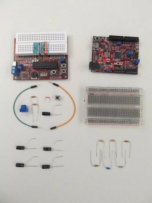
For this tutorial, I’ll be using the following supplies:
- A chipKIT board like the uC32 or DP32 from Digilent!
- A potentiometer (also known as a variable resistor). Mine is 10k Ohms, but I wished it was only 5k. Still, it’s what I had on hand and it worked.
- One 1.5k Ohm and one 220 Ohm resistor.
- A 1uF capacitor.
- A Button.
- A Breadboard.
It can also be super useful to have a selection of other capacitors and resistors to try out.
Step 3: First the Code…
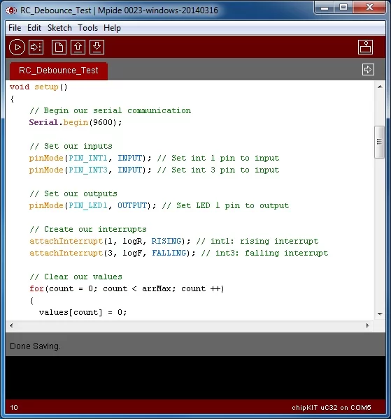
Start by downloading this test code. This code will work on either the uC32 or DP32. Just make sure you’ve selected the right board and serial port under Tools -> Board and Tools -> Serial Port.
(If you’ve never used MPIDE or the DP32 before, check out my Getting Started with the DP32 tutorial.)
This code works by using interrupts to record how long the button is held down. We set up two interrupts, one triggered on rising, and one on falling*. The rising interrupt checks how long it’s been since an interrupt was triggered (it would have been a falling interrupt), and records that as the time the button was pressed down. The falling interrupt does the same, and records this as how long the button was released.
The code records this time, specifically how long the button was pressed down, and uses it to turn off and on the LED. In the main code, it checks how long the LED has been on or off, and switches the state once it’s passed the recorded time.
*chipKIT boards based off the PIC32 microcontrollers (such as the DP32, uC32, WF32, etc.) do not have the hardware to do interrupts triggered on change. Only rising and falling.
Attachments
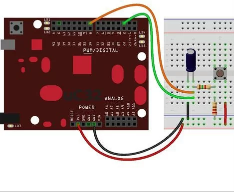
Step 4: … Then the Circuit!
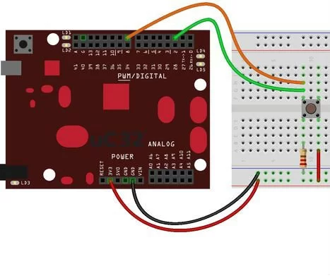
If this seems too simple to you, that’s because it is. We’re about to break this thing.
(Your board will be fine don’t worry.)
Step 5: Why Doesn’t This Work?
If you play with this circuit a little, you might think it works just fine, but check out the gif above. Instead of blinking, the light just stays solid. What’s happening?
This little glitch isn’t going to happen every time you press the button, but every once in a while (about one in ten times) your button will bounce on its way back up.
“But how does that effect the LED?”, you might ask, your curiosity piqued. Well a clue lies in the data your microcontroller is sending back to the computer. Check it out…
Step 6: Well There’s Your Problem…
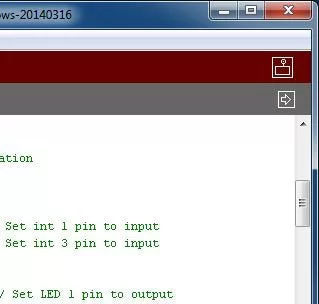
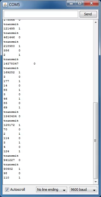
Open up your serial monitor by clicking the icon with a box and antenna in the top right corner of your MPIDE window (make sure your board is still plugged into the computer). You should see a blank white window pop up.
Now press your button. A few lines of numbers should appear in the window (similar to the second picture). These have been sent from your microcontroller!
Every time you trigger an interrupt on your board, your code records how long it’s been since the last interrupt was triggered. It also records whether the interrupt was triggered on a rising edge (pushing the button down) or a falling edge (releasing the button). It stores these values until the interrupts are finished being triggered. Then, the next time it gets a chance, it dumps all these stored values into the serial communication line, to be read by your computer.
That’s what you’re seeing appear on screen. Every time the line “transmit” appears, that’s the start of a new data dump from your board. Generally, for every rising and falling edge, the board finds time to transmit between interrupts, but that’s not guaranteed.
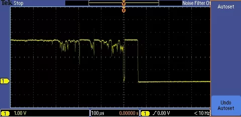
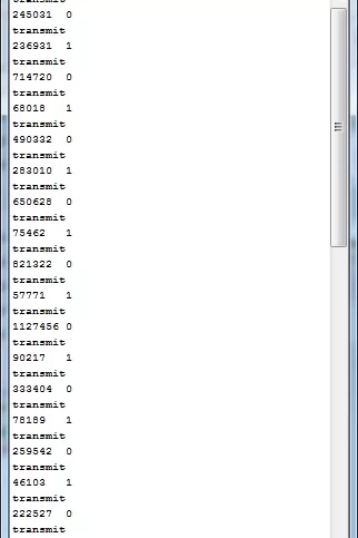
Check out the second picture. Here, our board doesn’t have time to transmit data, so it has to cache it until it gets a chance to dump it all at once. This happens because our button is bouncing, and the interrupts get triggered too quickly for our board to transmit. Look at how long each high and low value lasts. For this circuit, bounces can be as short as just a few microseconds, or as long as 400 microseconds.
Recall that our code records whatever the last “held down” time was, and uses this for the cycle time for our LED. When a bounce happens, that last “held down” time might be incredibly short! This means that the LED is made to blink very fast, giving it the appearance of being held on.
In order to get rid of these bounces, we’ll apply an RC filter.
Step 7: A Simple RC Filter
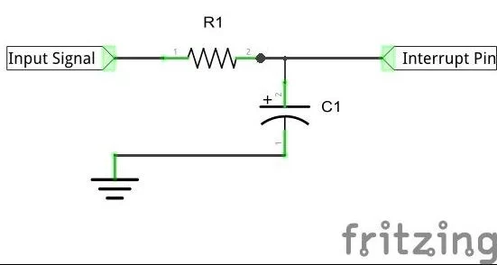
So what exactly is an RC filter and how does it work?
Well it’s a little like the shocks on your car. While the shocks on your car are there to smooth out jolts from bumps in the road, an RC filter smooths out jolts in electrical circuits!
The analogy can be extended further too. Your car’s shocks are made up of a spring and a pneumatic damper, and an RC filter has a capacitor and resistor.
Imaging a car that only has springs for it’s shocks, the ride would be really bouncy right? So we add a pneumatic damper to keep it from bouncing so much. Same thing with the RC filter. If we just used a capacitor, the signal would continue to be “bouncy”, so we add a resistor to dampen it.
“Okay,” I can hear you say, having just googled what a pneumatic damper is, “so how do we apply this to our circuit?”
Step 8: Picking Resistor and Capacitor Values
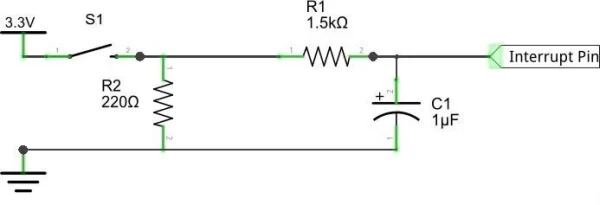
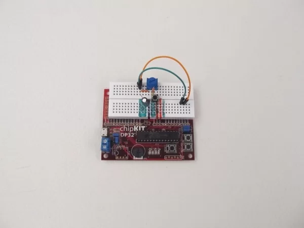
First think about what our input signal is. In the button circuit, we want to tell whether the button is pressed or not, so the output from our button is our input signal! Check out the schematic above to see how that fits into a circuit.
You may also notice that the values for the resistor and capacitor (R1 and C1) are 1.5k and 1u respectively. How did I get those values?
There is a very helpful tutorial explaining, in depth, how to go about picking R and C values for an RC filter on the Digilent Learn site, and I’d encourage you to check those out. I’m just going to go over the basics here.
It all boils down to the following formula:
5t ≤ R*C
In this formula, R is obviously your resistor value, and C is your capacitor value, but what is t?
Step 9: Finding T
Go back to the data you got back from your board, specifically after you’ve gotten it to bounce glitch a couple times. Some of those timing values are obviously intentional because they’re so large. Usually they’ll show up right after “transmit”. We want to ignore these and focus on the small values. These are our bounces, remember?
Look for the largest small value, that’ll be our longest bounce. In the picture above, that’s 386 microseconds. We’ll round this up to 400 microseconds. That’s our t.
Plugging that into our formula from before we get:
5(400) = 2000 ≤ R*C
Now we just need to pick R and C values that satisfy this equation!
In my experience, resistors are more abundant than capacitors, meaning I have more choice for resistor values. That means I want to pick a capacitor value first, and then find a resistor that fits. For convenience, I’ve picked a 1uF capacitor. That means I’ll want a resistor of at least 2kOhms.
But wait…
Step 10: Things Aren’t That Cut and Dried
… wasn’t our chosen resistor only 1.5kOhms? You’re right!
Turns out I don’t have a 2k resistor, so I tried out a couple and eventually settled on 1.5kOhms. So what’s going on?
Well the long and the short of it is that 1.5k just works. Recall that 400 microseconds was the time of our longest bounce. Most of our bounces were much shorter than that. So our 1.5k resistor will filter out most of our bounces without any problem (as you’ll see in our next step).
For now, just assemble the circuit above with a 1.5k resistor.
Step 11: Smooth Like Butter
Now try out your circuit! Try to make it glitch like before. It’s still possible, but it’s very difficult. I’ll bet you can’t manage without changing the circuit!
But wait! There’s more!
Recall that our equation for picking values for our resistor and capacitor was:
5t ≤ R*C
What’s that “less than or equal” sign doing in there? That means we could pick an extremely high R and C for our circuit, and still satisfy this equation, right? So why don’t we?
Well, let’s play around with some different resistor values and find out!
Step 12: Adjustable RC Filter
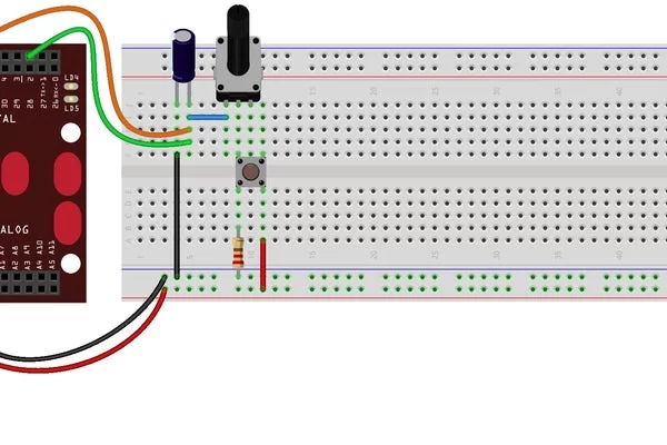
Here we go! By swapping out our resistor for a potentiometer (also called a variable resistor), we can easily see how different R values effect our circuit.
Try playing with the pot and seeing how the behavior changes! If you get your pot’s resistance low enough, you should start seeing bounce again, but if you get it too high, you’ll notice that the light seems to respond more slowly.
That’s why we want to make sure our equation (5t ≤ R*C) is as close to equal as possible. Too low, and it doesn’t perform, but too high, and it starts to make our circuit lag.
Step 13: Tuning Without Serial
Having an adjustable resistor isn’t just for exploring different R values. It also gives us a way to “tune” our R value without needing a serial port connected. We just need to observe the behavior of our light!
Recall that bounce causes the light to look like it’s holding steady (when in fact it’s actually blinking on and off too rapidly to see). There are, in fact, two different bounce behaviors that we need to watch out for: rising and falling bounce.
Check out the gifs above. In the first gif, the light stays solid after I’ve released the button. This is caused by falling bounce. As the button is released, the voltage seen by our interrupt pins falls down to ground. If it bounces on the way down, the board thinks there’s been a rapid button-press before the values fall all the way to ground. This causes our bounce glitch.
Now check out the second gif. In this one, the light stays solid until I release the button. In this case, our bounce happened on the rising edge. It is possible to get rid of either rising or falling bounce, without getting rid of the other*
By tuning our resistor until we no longer see either type of bounce, we can be sure to eliminate both, without needing to use our serial connection to find out how long our bounces are!
*To understand why, read the Digilent Learn module on debouncing button presses with RC filters. It’s explained that the circuit changes between button presses, and why this happens.
Step 14: But of Course the DP32 Is Weird…
By now, you may have noticed that I’ve been using the uC32 to demonstrate this circuit. The same circuit will work on the DP32, but unfortunately this weird little board has some additional behavior to explore.
As you play with your variable resistor on your DP32, you may notice that increasing the resistance too much will cause the button to stop responding (as in the first gif). As best as I can tell, that’s because the DP32’s pins “leak” more current when sensing voltage than the uC32’s do.
The solution to this problem is to adjust the resistance down again, until you see the light suddenly start to blink slowly, as if you’d held down the button for a very long time. To see how this is done, check out the second gif. I stop turning the pot immediately when I see the light turn off. Conveniently enough, that happens to be a very good resistance for my RC filter!
Step 15: Where Is This Leading?
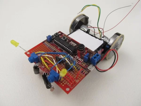
“Hrrrm,” you may say, your hand tucked under your chin, deeply in thought. “I feel like you’re leading somewhere with all this.” You’d be right too!
I’ve hintedseveraltimes in my previous I’bles that I’m working towards a project that I think is really cool. That project has been delayed and complicated by outside forces (sometimes referred to as “life”) but I’m back on track and closer than ever to completing that project and showing you guys how cool it really is!
For now, I just hope you find this tutorial on debouncing interrupts useful and interesting! I’ll see you guys again soon!