Summary of CONTROL OF SATELLITE ANTENNA WITH PIC16F877
This article describes a low-cost, dual-axis automatic antenna rotor controller for amateur radio satellite tracking using a PIC16F877 microcontroller. It interfaces with PC software like FODtrack via a serial port to control azimuth and elevation rotors. The system compares target positions from the computer with analog feedback from potentiometers on the rotors to drive up/down/left/right motor switches.
Parts used in the Dual-Axis Rotor Control Interface:
- PIC 16F877 microcontroller IC
- Transistor drivers
- Satellite tracking software (e.g., FODtrack)
- Serial (COM) port connection
- Azimuth and elevation rotors
- Position feedback potentiometers
- On-chip ADC
- Crystal clock oscillator (10 MHz)
the dual-axis rotors control interface . Here is a low cost automatic antenna rotor controller specifically developed for amateur radio satellite tracking operations. This rotor control interface is quite simple to construct. The circuit consists only one PIC 16F877… Electronics Projects, Control of Satellite Antenna with PIC16F877 “microchip projects, microcontroller projects, pic assembly example, pic16f877 projects,
the dual-axis rotors control interface . Here is a low cost automatic antenna rotor controller specifically developed for amateur radio satellite tracking operations. This rotor control interface is quite simple to construct. The circuit consists only one PIC 16F877 microcontroller IC and a few transistor drivers. Please take a moment and look around. You might find something useful !
Satellite tracking is done most commonly on a computer with a satellite tracking software. The FODtrack ( by XQ2FOD ) software, which I am experimenting with this control interface, is available for download at www.amsat.org. It uses serial ( COM ) port ( baud 1200 ) on your PC to drive the external azimuth and elevation rotors to position the antenna via the interface described here. The data format of the GS-232 output command from the COM port is in the form of Wxxx yyy, where xxx is the azimuth and yyy is the elevation angle. GS-232 command received via the PIC16F877 uart serial port is converted and stored as 8-bits binary azimuth and elevation target position values into the microcontroller on-chip ram area. Analog input signals from the rotators position feedback pots ( 0 to 5 volts for azimuth from 0 to 360 degrees, 0 to 2.5 volts for elevation from 0 to 180 degrees ) are converted by the on-chip ADC into binary values which subsequently are compared with the target position values to produce outputs to control the up, down and left, right switches.
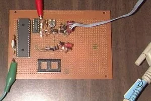
SATELLITE TRACKING INTERFACE
![]()
Assembler software to program the PIC16F877 is available for download at www.microchip.com and the P16PRO printer port PIC eprom programming software is available for download at www.picallw.com.
PIC16F877 microcontroller uart serial port baud rate is 1200 and the crystal clock frequency is 10 MHz. The two-axis ( azimuth and elevation ) rotor drive output pins are RB1, RB2, RB4 and RB5. Rotors position analog input pins are AN0/RA0 and AN1/RA1.
Source: geocities.com/yyz228 Control schematic Satellite Antenna with PIC16F877 pic assembly source code alternative link:
FILE DOWNLOAD LINK LIST (in TXT format): LINKS-1328.zip
Source: CONTROL OF SATELLITE ANTENNA WITH PIC16F877
- What is the primary purpose of this interface?
It is a low cost automatic antenna rotor controller developed specifically for amateur radio satellite tracking operations. - How does the system receive position commands?
The PIC16F877 receives GS-232 format data via a serial COM port running at 1200 baud from satellite tracking software. - What voltage range do the azimuth potentiometers provide?
The azimuth position feedback pots supply an analog signal ranging from 0 to 5 volts corresponding to 0 to 360 degrees. - Which pins are used for the rotor drive outputs?
The two-axis rotor drive output pins are RB1, RB2, RB4, and RB5. - How is the current rotor position determined?
Analog input signals from the rotator position feedback pots are converted by the on-chip ADC into binary values. - What is the crystal clock frequency required?
The PIC16F877 microcontroller operates with a crystal clock frequency of 10 MHz. - Can I find the assembler software online?
Yes, assembler software to program the PIC16F877 is available for download at www.microchip.com. - What software format is used for the serial output?
The data format is Wxxx yyy, where xxx represents the azimuth angle and yyy represents the elevation angle.