Summary of contactless tachometer circuit with code
This article details the design of a Contactless Digital Tachometer using an 8051 Microcontroller to measure motor speed in RPM without physical contact. It utilizes an IR reflective sensor pair, a comparator circuit, and a 7-segment display for output. The system operates on retro-reflective scanning principles where an IR LED emits light detected by a photo diode upon reflection from a rotating object.
Parts used in the Contactless Digital Tachometer:
- 8051 Microcontroller
- 8051 Development Board
- 8051 Microcontroller Programmer
- IR Sensor Module (Reflective Type)
- 4 – Digit 7 – Segment Display
- 4 x 2N2222 NPN Transistors
- 4 x 470Ω Resistors (1/4 Watt)
- 8 x 100Ω Resistors (1/4 Watt)
- 11.0592 MHz Quartz Crystal
- 2 x 33pF Ceramic Capacitors
- 2 x 10 KΩ Resistor (1/4 Watt)
- 10 µF Capacitor (Polarized)
- Push Button
- 1 KΩ x 8 Resistor Pack
A Tachometer is a device which measures the speed of a rotating object like an electric motor or a crank shaft of a vehicle engine. Speed of an electric motor is determined by the number of revolutions made by the motor in one minute. In other words, speed is measured in RPM (Revolutions per Minute). Here, in this project, we designed a simple Non – Contact or Contactless Digital Tachometer using 8051 Microcontroller, which can measure speed with an accuracy of 1 rev/sec.
Principle Behind the Circuit
The basic principle behind the Contactless Digital Tachometer involves a simple embedded system with a sensor, a controller and an actuator. The sensor used here is Infrared (IR) transmitter – receiver pair, the controller used is the 8051 Microcontroller loaded with a compiled code and the actuator is a display device, for displaying the speed of the motor.
The sensor senses the speed of the motor without actually being in contact with it by the principle of light transmission and reflection and generates a signal. This signal is converted into an electric signal and fed to the microcontroller, which is programmed to calculate the speed in terms of number of motor revolutions in one minute. This speed is displayed on the 7-segment display.
Construction and Output Video
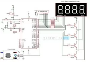
Contactless Digital Tachometer Circuit
A Tachometer is basically used to measure angular speed of a motor. It can be mechanical device with a warm gear and spindle arrangement or an electrical device which converts the angular speed into electrical signal. The electrical tachometer in turn can be an AC tachometer or a DC tachometer.
While a conventional tachometer is a contact tachometer, which can produce erroneous results due to change in contact parameters, a Contactless digital tachometer is preferred which doesn’t requires any contact with the device whose speed is to be measured.
It basically works on the principle of retro reflective scanning, wherein a light source device like LED transmits light signal to the retro reflective target device which reflects the light, which is in turn received by the light detector.
Circuit Diagram of Contactless Digital Tachometer
Components Required
- 8051 Microcontroller
- 8051 Development Board
- 8051 Microcontroller Programmer
- IR Sensor Module (Reflective Type)
- 4 – Digit 7 – Segment Display
- 4 x 2N2222 NPN Transistors
- 4 x 470Ω Resistors (1/4 Watt)
- 8 x 100Ω Resistors (1/4 Watt)
- If Development Board is not used, then you need
- 11.0592 MHz Quartz Crystal
- 2 x 33pF Ceramic Capacitors
- 2 x 10 KΩ Resistor (1/4 Watt)
- 10 µF Capacitor (Polarized)
- Push Button
- 1 KΩ x 8 Resistor Pack
How to Design Contactless Digital Tachometer?
Sensor Circuit Design
The sensor circuit consists of an IR transmitter and an IR receiver. An IR LED is used as the transmitter and a photo diode is used as the receiver. A reflective type of IR sensor is used in this project. In this type, the IR transmitter and receiver are placed side -by – side.
The IR transmitter circuit is very simple. The anode of the IR transmitter is connected to 5V supply and the cathode is connected to ground through a current limiting resistor of 150Ω. Thus, the IR transmitter starts emitting infrared rays.
IR receiver used in the project is a photo diode and it must be connected in reverse bias. The negative terminal or cathode is connected to 5V supply and the positive terminal or anode is connected to ground through a current limiting resistor of 10KΩ.
And finally, the output of the IR receiver is given to the comparator. The comparator compares the input from the IR receiver with a reference value (which is given through a 10KΩ Potentiometer). If the input from the IR receiver is greater than the reference value, the output of the comparator will be HIGH or else, the output will be LOW.
The following image shows the circuit diagram of the Reflective type IR Sensor used in this project.
Source: contactless tachometer circuit with code
- What is the primary function of this device?
A tachometer measures the speed of a rotating object like an electric motor or crankshaft in RPM. - How does the sensor detect speed without contact?
It uses retro-reflective scanning where an IR transmitter sends light that reflects off a target to a receiver. - What controller is used in this project?
The project uses an 8051 Microcontroller loaded with compiled code. - Can this device measure speed with high accuracy?
Yes, it can measure speed with an accuracy of 1 rev/sec. - What components make up the sensor circuit?
The sensor circuit consists of an IR LED transmitter and a photo diode receiver placed side-by-side. - How is the final speed value displayed?
The calculated speed is shown on a 4-digit 7-segment display. - What happens if a development board is not used?
You will need additional components including a quartz crystal, capacitors, resistors, a push button, and a resistor pack. - Does the IR receiver operate in forward or reverse bias?
The photo diode receiver must be connected in reverse bias.