Summary of Circuit Simulator
The article explains how to use an LRC circuit simulator, detailing interface elements like color-coded voltages and current indicators. It covers interacting with components via clicking, right-clicking for editing, and using graphs as oscilloscopes. Users can access sample circuits, adjust variable components with sliders or scroll wheels, and create blank circuits. The "Draw" menu allows adding wires and components, while selection mode enables moving and resizing parts.
Parts used in the LRC Circuit Simulator:
- LRC Circuit
- Switches
- Voltage Sources
- Potentiometers
- Variable Voltage Sources
- Wires
- Oscilloscope Graphs (Voltage and Current)
- Sliders
How to use this
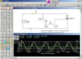
When the simulator starts up you will see an animated schematic of a simple LRC circuit. The green colour indicates positive voltage. The grey colour indicates ground. A red colour indicates negative voltage. The moving yellow dots indicate current.
To turn a switch on or off, just click on it. If you move the mouse over any component of the circuit, you will see a short description of that component and its current state in the lower right corner of the window. To modify a component, move the mouse over it, click the right mouse button (or control-click if you have a Mac) and select “Edit”. You can also access the edit function by double-clicking on a component.
There are three graphs at the bottom of the window; these act like oscilloscopes, each one showing the voltage and current across a particular component. Voltage is shown in green, and current is shown in yellow. The current may not be visible if the voltage graph is on top of it. The peak value of the voltage in the scope window is also shown. Move the mouse over one of the scope views, and the component it is graphing will be highlighted. To modify or remove a scope, click the right mouse button over it and choose “remove” from the menu. There are also many other scope options in this context menu. To view a component in the scope, click the right mouse button over the component and select “View in Scope”.
The “Circuits” menu contains a lot of sample circuits for you to try.
Some circuits, eg Basics->Potentiometer, contain potentiometers or variable voltage sources. These can be adjusted using sliders that are added to the right hand tool bar, or by positioning the mouse pointer over the component and using the scroll wheel.
You can get a blank circuit by choosing “Blank Circuit” from the “Circuits” menu. You will need to add at least one voltage source to start the simulator.
To add components or a wire choose one of the “Add….” options from the “Draw” menu. Note that common components have keyboard short-cuts to select their add mode. When in add mode the cursor changes to a “+”. Click and drag the mouse to add a component.
Components may be moved and resized in the selection mode. When in selection mode the cursor changes to an arrow. Choose “Select/Drag Sel” from the “Draw” menu or press “space”, or press “escape” to go in to selection mode. Hovering over a component will highlight it and show information about that component in the info area. Clicking and dragging on a component will move the component. If you click and drag on the square handles or hold down the ctrl key this will resize the component and move the terminals.
For more detail: Circuit Simulator
-
What do the colors green, grey, and red indicate?
Green indicates positive voltage, grey indicates ground, and red indicates negative voltage. -
How do I turn a switch on or off?
You simply click on the switch to toggle its state. -
How can I modify a component in the simulator?
Move the mouse over the component, click the right mouse button (or control-click on Mac), select Edit, or double-click the component. -
What is the function of the three graphs at the bottom?
They act like oscilloscopes showing voltage in green and current in yellow across specific components. -
How can I adjust potentiometers or variable voltage sources?
You can use the sliders added to the right-hand toolbar or position the mouse pointer over the component and use the scroll wheel. -
How do I add new components or wires to the circuit?
Select one of the Add options from the Draw menu, then click and drag the mouse where you want to place them. -
How can I move or resize components after placing them?
Enter selection mode by pressing space or escape, then click and drag to move; use square handles or hold ctrl to resize.