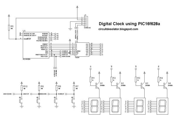
Summary of Circuit Digital Clock Using PIC16f628a Microcontroller Schematics
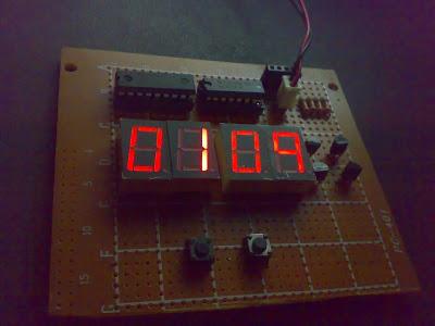
This article describes a simple digital clock project built with a PIC16F628A microcontroller, using timer interrupts to count minutes and multiplexed seven-segment display control via PORTB and PORTA pins. The code initializes timers, handles timekeeping in an ISR, and cycles display digits through a multiplexer. The clock requires manual start at 12:00.
Parts used in the Digital Clock using PIC16f628a:
- PIC16F628A microcontroller <li.Seven-segment displays (4 digits) <li.Resistors (current limiting for displays) <li.Wires and PCB or breadboard <li.Power supply (suitable for PIC16F628A) <li.Clock crystal 4 MHz or oscillator matching _XTAL_FREQ <li.Capacitors for decoupling and oscillator stability <li.Transistor drivers or multiplexing hardware if required
You need to start up you’re clock at exactly 1200am/pm.
 ——————————————-SOURCE CODE———————————————–
//Digital Clock using PIC16f628a microcontroller
//Design by: circuit_desolator
//Date: April 2011#include<htc.h>
#define _XTAL_FREQ 4000000
__CONFIG(INTIO & WDTDIS & PWRTDIS & UNPROTECT & BORDIS & LVPDIS);
unsigned int hours = 0;
unsigned int mins = 59;unsigned int timer = 0;
unsigned char mpx_cnt = 0;
static unsigned char mode = 0;void interrupt ISR(void)
{{
timer++;if(timer > 19650)
{
mins++;
if(mins == 60)
{
mins = 0;
hours++;
if(hours == 13)
hours == 1;
}timer = 0;
}
}switch (mpx_cnt)
{
case 0:
PORTB = hours/10;
RA0 = 1;
mpx_cnt = 1;case 1:
PORTB = hours%10;
RA1 = 1;
mpx_cnt = 2;case 2:
PORTB = mins/10;
RA2 = 1;
mpx_cnt = 3;case 3:
PORTB = mins%10;
RA3 = 1;
mpx_cnt = 0;
}T0IF = 0; //clear TMR0 interrupt flag
}
void init_Timers(void)
{
GIE = 0;T0CS = 0;
PSA = 0;
PS2 = 0;
PS1 = 0;
PS0 = 0;T0IF = 0;
T0IE = 1;
TMR0 = 6;GIE = 1;
}void main()
{
TRISA = 0x00;
TRISB &= ~0x0F;
TRISB |= 0xF0;init_Timers();
while(1);
}
—————————————SOURCE CODE——————————————–
For more detail: Circuit Digital Clock Using PIC16f628a Microcontroller Schematics
- What microcontroller is used in the project?
The project uses a PIC16F628A microcontroller. - How is time advanced in the code?
Time is advanced inside the interrupt service routine by incrementing a timer variable and increasing minutes when timer exceeds 19650. - How many display digits are multiplexed?
Four digits are multiplexed: two for hours and two for minutes. - How are the display digits driven in the ISR?
The ISR writes digit values to PORTB and enables corresponding RA0–RA3 lines for each digit in a switch sequence. - What frequency is defined for the oscillator?
The code defines _XTAL_FREQ as 4000000 (4 MHz). - How should the clock be started?
You need to start the clock exactly at 12:00 AM or PM as noted in the article. - Which timer is configured for interrupts?
The code configures TMR0 (Timer0) with T0CS cleared and enables its interrupt T0IE. - How is TRIS configured for ports A and B?
TRISA is set to outputs (0x00); TRISB lower nibble is set as outputs and upper nibble as inputs using TRISB &= ~0x0F and TRISB |= 0xF0.