Summary of chipKIT Tutorial 5: Pulse width modulation (PWM)
PWM controls average power by varying a digital signal’s duty cycle. This tutorial shows using chipKIT Uno32 PWM pins to fade two LEDs alternately by changing duty cycles with analogWrite(0–255). Pins 3 and 5 drive red and green LEDs through 100 Ω resistors; the sketch increments/decrements PWM counts to create opposite fading. LEDs can be driven directly; higher-current loads like DC motors require an external driver such as an H-bridge.
Parts used in the PWM LED Fade Project:
- chipKIT Uno32 board
- Red LED
- Green LED
- 100 Ω resistors (two)
- Breadboard
- Jumper wires
Pulse width modulation (PWM) is a technique of controlling the amount of power delivered to an electronic load using an on-off digital signal. The key idea behind this technique is that the average DC value of the digital signal, and hence the power delivered to the load, can be varied by varying the duty cycle of the signal. This method is commonly used for controlling speeds of DC motors and brightness of lamps. The switching mode power supplies are also based on the PWM technique. In this tutorial, we will discuss about the PWM pins of the chipKIT Uno32 board and illustrate the concept by controlling the brightness of two external LEDs.
Theory
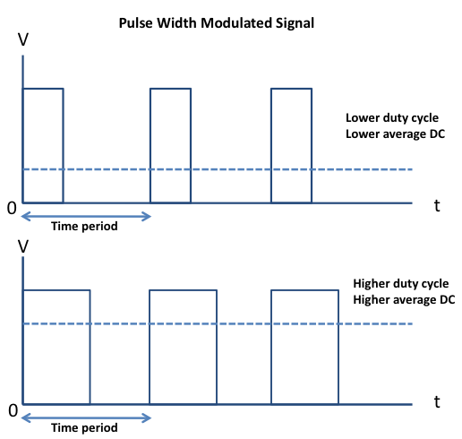
Pulse-width modulation (PWM) is a way of delivering energy through a succession of pulses rather than a continuously varying signal. By increasing or decreasing the pulse width (while frequency remaining unchanged), it is possible to control the output power. The fraction of the period for which the signal is on is known as the duty cycle. The average DC value of the signal can be varied by varying the duty cycle. The duty cycle can be anywhere between 0 (signal is always off) to 1 (signal is constantly on). Suppose, if the signal has +5 V while it is on and 0 V during off condition, then by changing the duty cycle of the signal, any voltage between 0-5 V can be simulated. This method is commonly used for controlling speeds of DC motors and brightness of lamps. The principle of PWM is illustrated in the picture below.
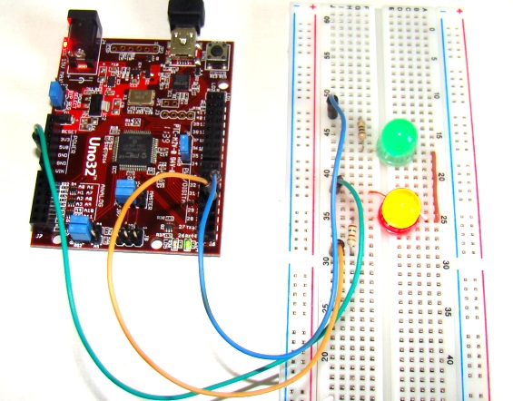
Circuit setup
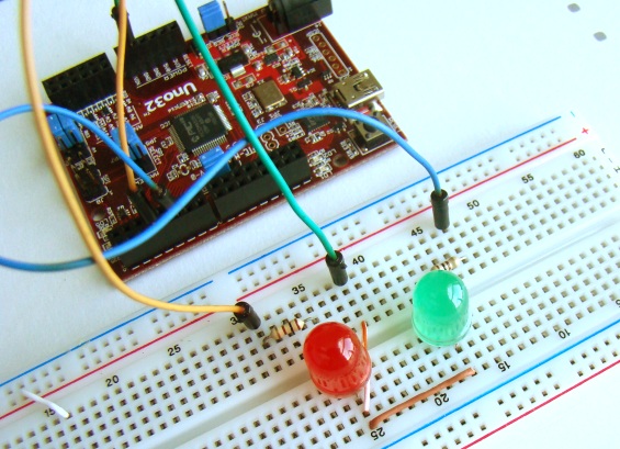
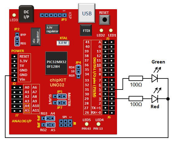
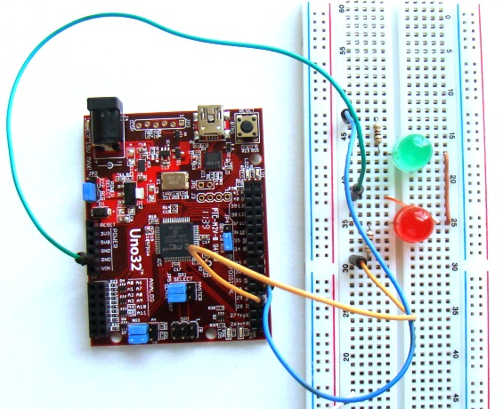
Actual setup on breadboardOn chipKIT Uno32 board, the I/O pins 3, 5, 6, 9, and 10 can be configured to provide PWM outputs. We will connect two LEDs (red and green) to PWM pins 3 and 5 and control their brightness by varying the duty cycles of the PWM signals driving those LEDs. Two 100? resistors are used to limit the current through the LEDs.
Writing sketch
PWM signals in an Arduino platform can be generated using analogWrite() command. Inside the parenthesis, you specify the pin number and the desired duty cycle (0-255). Duty cycle of ‘0’ corresponds to always off and ‘255’ corresponds to always on. When the analogWrite() is called, a steady square wave with the specified duty cycle is generated at the specified PWM pin. The following sketch controls the output power delivered to the two LEDs using varying duty cycle PWM signals. The two LEDs fade in and out alternately, which means when one is at peak intensity, other is dimmed low, and vice-versa.
int redLED   = 3;     // Red LED is connected to pin 3
int greenLED = 5;     // Green LED is connected to pin 5
int redCount   = 255; // Initial PWM values, RED is full
int greenCount = 1;   // Green is dim
int i = 0;

void setup()
{
  pinMode(redLED,   OUTPUT);
  pinMode(greenLED, OUTPUT);
}

void loop()
{
  if (i < 255)      // First phase
  {
    redCount   = redCount-1;   // Red down
    greenCount = greenCount+1; // Green up
   }
  else if (i < 509) // Second phase
  {
   redCount  = redCount+1;    // Red up
   greenCount = greenCount-1; // Green down
  }
  else              // Re-set
  {
    i = 0;
  }
  i += 1;
  analogWrite(redLED,   redCount);   // Write current values to LED pins
  analogWrite(greenLED, greenCount);

  delay(10);        // Pause for 10 millisecond
}
Output
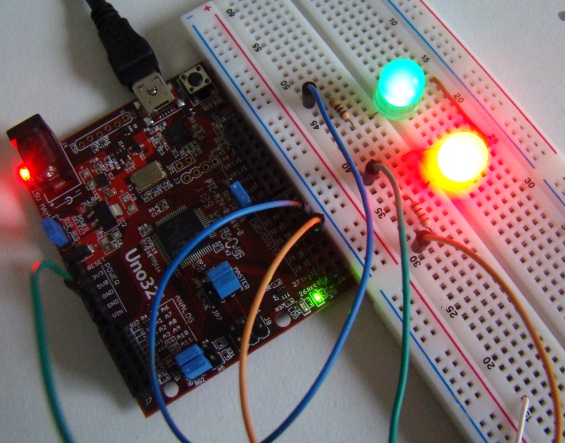
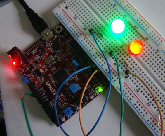
LEDs operate at very low current and, therefore, it was feasible to drive them directly through the PWM outputs from the UNO32 board. For DC motor control, an external motor driver circuit, such as H-bridge, is required, which basically amplifies the low current PWM signals coming from the microcontroller pins into high current PWM signals capable of sourcing enough current to drive the motor.
- What is PWM?
PWM is a technique of controlling power by varying the duty cycle of a digital on-off signal to change its average DC value. - Which Uno32 pins are used for PWM in this project?
Pins 3 and 5 are used to provide PWM outputs to the two LEDs in this project. - How is brightness controlled in the Arduino sketch?
Brightness is controlled with analogWrite using duty cycle values from 0 to 255 for each PWM pin. - What resistor value is used with the LEDs?
Two 100 Ω resistors are used to limit current through the LEDs. - Can the Uno32 drive DC motors directly with PWM?
No, for DC motor control an external motor driver such as an H-bridge is required to amplify current. - How do the two LEDs behave in the sketch?
The two LEDs fade in and out alternately: when one is at peak intensity the other is dim. - What analogWrite value corresponds to always off and always on?
analogWrite value 0 corresponds to always off and 255 corresponds to always on. - What delay is used between PWM updates in the loop?
The sketch uses a delay of 10 milliseconds between updates.