Summary of Building Keyless Car Alarm
This article details a DIY Keyless Entry (PKE) alarm system for cars, utilizing a PIC16F877A microcontroller and an AMS AS3933 LF receiver. The project replaces traditional door handle buttons with a piezo sensor on the windshield to trigger the 125kHz signal. It employs a 3V CR2032 battery-powered remote using an HT12E encoder and an Arduino-compatible library for the AS3933 chip to handle frequency detection and pattern matching between the car and the key fob.
Parts used in the PKE Alarm System:
- PIC16F877A microcontroller
- AMS AS3933 LF receiver IC
- HT12E encoder
- Piezo sensor
- CR2032 3V battery
- Premo antenna tuned at 125kHz
- Pushbuttons
- Cut car key
- Arduino-compatible AS3933 library
Most high-end modern vehicles come with keyless car Alarm or PKE:
as the name says in the key less car you do not have to use any key to unlock/lock the doors neither start the car engine.
to unlock or lock the doors the driver just presses on the small black button mounted at the door handle, and pressing the engine start button while pressing on the brake pedal will start the engine.
briefly the system works by using 2 bands for communication the LF band (usualy 125khz) and RF band (300 ~ 400+ Mhz). when the driver presses on the door handle key the car will transmit a code at the LF band, if the remote is within the range of the coverage which is not more that 5 meters the the remote recevie the signal and demodulated signal code matches between the car and the remote then the remote will reply a signal at the RF band and again if the code signal is valid the car will unlock and give access to start and drive.
you can search on google and read more about pke alarms.
In this project I’m going to build PKE alarm system for my car
Step 1: The Car Alarm

I chosed the pic16f877a uc for the car alarm but you can arduino , avr or any other uc
the car wires that connects to the alarm systme are as following :
+12 v
ground
2 wires to lock and unlock doors
2 wires for signal light
horn or siren wire (optional)
door switch (active low)
hand brake (active low)
brake pedel (active high)
fuel pump (active high to check is the engine running or not)
IGN
ACC
Start
so generally there are about 12 I/O needed
since it is keyless there are two buttons one is the door handle button and the other one is engine start button
and 1 PWM output for the (125khz antenna )
here is the link to the source code :
https://github.com/warshaa/PKE_Alarm/
instead of using the black pushbutton on the door handle to lock/unlock the doors, I used a piezo mounted on the front windshield so instead of pushing the button I have to knock the windshield then the alarm will wake up and send a 125khz signal
Step 2: The Car Remote

the remote is powered by 3v cr2032 battery
I used the premo antenna tuned at 125khz
the ams As3933 can detect LF frequency at as levels as low as few uVrms then it amplify the signal and demodulate it.
I used this library on github to program the as3933:
https://github.com/LieBtrau/arduino-as3933
There are two modes which are either frequency detect only, in this mode the as3933 will output high on the wake pin whenever it detects signal at the specific programmed frequency.
the other mode is pattern mode either single or double pattern in this mode the as3933 will compare the received pattern with the one which is preprogrammed in the chip if it matches it will output High on the wake pin.
you can read mode about this ic on the datasheet linked below:
http://www1.futureelectronics.com/doc/AUSTRIAMICRO…
also I chose the HT12E as an encoder which wasn’t good choice because of the low security of the device however it was pretty simple to implement and use.
it has 4 digital inputs so I connected 3 of them to 3 pushbuttons and the other one to the wake signal from the as3933
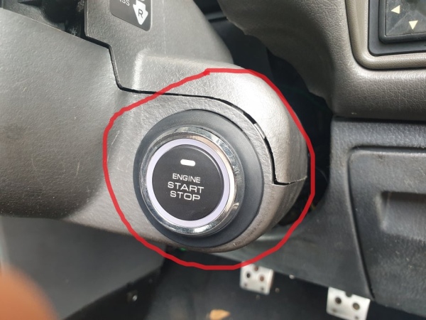
Step 3: The Installation

as mentioned earlier about the main wires for any car system I connected these wires to the car alarm. also I installed a push button in the key place. but before that I cut the car key and placed it in the key place to keep the steering wheel unlocked all the times.
here is the video of the project:
that’s it I hope you find this project useful , if you have any quetions feel free to comment below
Source: Building Keyless Car Alarm
- How does the system unlock the car doors?
The driver presses a button on the door handle or knocks the windshield, causing the car to transmit a 125kHz LF signal; if the remote within 5 meters replies with a valid RF code, the doors unlock. - What communication bands are used in this PKE system?
The system uses two bands: LF band at 125kHz for the initial signal and RF band between 300 and 400+ MHz for the reply. - Can I use an Arduino instead of the PIC16F877A?
Yes, the author states that you can use an Arduino, AVR, or any other microcontroller instead of the chosen PIC16F877A. - How is the remote powered in this project?
The car remote is powered by a 3V CR2032 battery. - What happens if the received signal pattern matches the preprogrammed one?
In pattern mode, if the received pattern matches the preprogrammed data in the AS3933 chip, it outputs High on the wake pin. - Why did the author choose the HT12E encoder despite its low security?
The HT12E was chosen because it was pretty simple to implement and use, even though it has low security. - How does the author replace the door handle button function?
A piezo sensor mounted on the front windshield is used so the user must knock the windshield to wake up the alarm and send the 125kHz signal. - What is the maximum range for the remote to receive the signal?
The coverage range for the remote to receive the signal is not more than 5 meters.