Summary of Automatic Power Factor Controller using Microcontroller
This article details an Automatic Power Factor Correction (APFC) prototype using a PIC Microcontroller to minimize energy wastage in inductive loads. The system monitors voltage and current waveforms, calculates the power factor, and automatically engages capacitors via relays when the factor drops below 0.9 to bring it closer to unity.
Parts used in the Automatic Power Factor Controller:
- Voltage Transformer
- Current Transformer
- LM358 Op-amp
- PIC 16F877A Microcontroller
- 16×2 LCD Display
- Relay
- ULN2003 Driver IC
- Power Factor Correcting Capacitor
The thirst for new sources of energy is unquenchable, but we seldom realize that we are wasting a part of the electrical energy every day due to the lagging power factor in the inductive loads we use. Hence there is an urgent need to avoid this wastage of energy.
Before getting into the details of Power factor correction, lets just brush our knowledge about the term “power factor”. In simple words power factor basically states how far the energy provided has been utilized. The maximum value of power factor is unity. So closer the value of P.F to unity, better is the utility of energy or lesser is the wastage. In electrical terms Power factor is basically defined as the ratio of the active power to reactive power or it is the phase difference between voltage and current. Active power performs useful work while Reactive power does no useful work but is used for developing the magnetic field required by the device.
Most of the devices we use have power factor less than unity. Hence there is a requirement to bring this power factor close to unity. Here we are presenting a prototype for automatic power factor correction using PIC Microcontroller.
Circuit Diagram
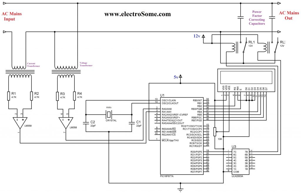
Working
Comparator Section
The 230 V, 50 Hz is step downed using voltage transformer and current transformer is used to extract the waveforms of current. The output of the voltage transformer is proportional to the voltage across the load and output of current transformer is proportional to the current through the load. These waveforms are fed to Voltage Comparators constructed using LM358 op-amp. Since it is a zero crossing detector, its output changes during zero crossing of the current and voltage waveforms. These outputs are fed to the PIC which does the further power factor calculations.
Microcontroller Section
Correction Section
Power Factor Correcting capacitor connected parallel to load through relay, if the relay is energized by microcontroller it will connect the capacitor parallel with load, if relay deenergized it will remove the capacitor from the load. When the resistive load is on the power factor will be near to unity so the microcontroller doesn’t energize the relay coil. When the inductive load is on the power factor decrease now the microcontroller energize the relay coil in order to compensate the excessive reactive power. Hence according to the load the power factor is corrected.
For more detail: Automatic Power Factor Controller using Microcontroller
- Why is there an urgent need to avoid energy wastage?
Because we waste electrical energy daily due to the lagging power factor in inductive loads. - What defines power factor in electrical terms?
It is defined as the ratio of active power to reactive power or the phase difference between voltage and current. - How does the microcontroller calculate the power factor?
It finds the tangent of the ratio between the time of zero crossing differences of current and voltage waveforms. - When does the relay switch on the capacitor?
The relay switches on the capacitor if the calculated power factor is less than 0.9. - What role does the ULN2003 play in this project?
The ULN2003 acts as a driver IC consisting of seven Darlington pairs to switch the relays. - How does the capacitor correct the power factor?
The current lead in the capacitor compensates for the current lag usually present in loads, reducing the phase difference. - Does the microcontroller energize the relay when a resistive load is on?
No, because the power factor is near unity with a resistive load, so the microcontroller does not energize the relay coil. - What happens when an inductive load is connected?
The power factor decreases, causing the microcontroller to energize the relay coil to compensate for excessive reactive power.