
Summary of Analog Input Using PIC Microcontroller (assembly Language)
This tutorial shows how to read an analog input with a PIC microcontroller (PIC16F887) using assembly language, covering hardware hookup with a PICkit programmer and breadboarded 40-pin chip, MPLAB X IDE project setup using mpasm, configuring PICkit power, adding an .asm source file, and running the program. It notes required pull-up on MCLR and links to a C-based alternative and SFR explanations for ADC.
Parts used in the Analog Input Using PIC Microcontroller (assembly Language):
- PIC16F887 microcontroller (40-pin)
- PICkit programmer
- Breadboard (for plain chip setup)
- Wires/jumpers
- 4.7k-10k resistor (pull-up for MCLR)
- Power supply (VDD and VSS connections, e.g., 3.375 V)
- Optional development/demo board (if not using breadboard)
- Computer with MPLAB X IDE installed
- mpasm assembler (selected in MPLAB)
- General purpose analog input source (sensor or potentiometer for ADC input)
So this tutorial should show you how to get an analog input using a PIC microcontroller (I’m using a PIC16f887) in assembly language. You may have a demo board (which makes programming way easier) just a chip. I’m using just a plain 40 pin chip on a breadboard.
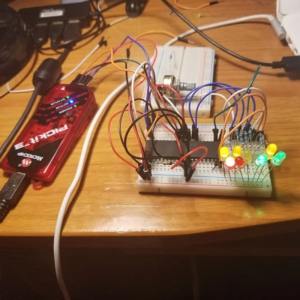
Step 1: Hardware Setup
-You will need a PICkit programmer
- I am using a PIC chip on a breadboard. If you are using a dev board then you can probably disregard some of this since it should plug right in. I have the following setup:
- Hookup VDD and VSS between PICkit and chip (there may be multiple VDD,VSS pins…connect them all)
- PICkit MPCLEAR to MPCLEAR PIN of chip
- MPLCLEAR PIN of chip has 4.7k-10k resistor (this is important) connected to VDD (if you are just using a chip only)
- PGD pin of PICkit to PGD on board
- PGC pin of PICkit to PGC on board
- PGM pin on PICkit is left unconnected
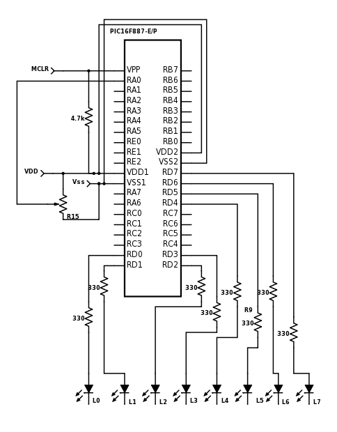
Follow the attached diagram to hookup the the entire circuit.
Step 2: Software Setup
 ‘
‘You need MPLAB X IDE installed if you don’t have it already.
- Open MPLAB
- File->New Project
- Microchip Embedded->Standalone Project
- Select Your Chip from the list (mine is a 16F887)
- Select PICkit under the hardware tools
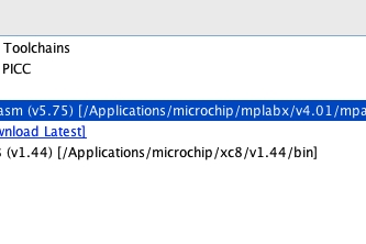
- Select mpasm
- Set your project name and save locations
Now that you created the project, let’s configure some of the properties
- In the project tree that just got created on the left, right click the project and select properties
- Select PICKit on the left hand side
- Select power from the dropdown list
- Check the power the target device and set the voltage level 3.375
- In the project tree, right click the source folder and add a general asm file
- Open the .asm file and past the code from the attached .txt file
Step 3: Wrap-up
Assuming there was no copy and paste formatting errors and you changed the appropriate code if you use a different microcontroller, you should be ready to hit the green play button.
Check this out if you want to see how to essentially do this in C instead of assembly while still using MPLAB. There is also a good explanation of some of the special function registers (SFRs) used in analog to digital conversion in it as well.
- What hardware is required to follow this tutorial?
PIC16F887 (or chosen PIC), PICkit programmer, breadboard or dev board, wires, 4.7k-10k resistor for MCLR pull-up, power supply, and a computer with MPLAB X IDE. - Do I need a 4.7k-10k resistor and where does it go?
Yes, a 4.7k-10k resistor is required as a pull-up on the MCLR pin to VDD when using a standalone chip. - How do I connect the PICkit to the PIC chip?
Connect VDD and VSS between PICkit and chip (all VDD and VSS pins), PICkit MCLR to chip MCLR, PGD to PGD, PGC to PGC; leave PGM unconnected. - What software setup is needed to program the PIC in assembly?
Install MPLAB X IDE, create a new Standalone Project for your PIC, choose PICkit as hardware and mpasm as assembler, set PICkit power to power the target at 3.375 V, and add a general .asm source file with the provided code. - Can I use a development board instead of a breadboard?
Yes, if using a dev board you can likely disregard some wiring steps since the board usually provides required connections. - What should I do after adding the .asm file to the project?
Paste the provided assembly code into the .asm file, ensure any microcontroller-specific changes are made, then build and hit the green play button to program and run. - What voltage should I set PICkit to supply to the target?
Set the PICkit to power the target device and set the voltage level to 3.375 V as indicated in the tutorial. - Is there an alternative example in another language?
Yes, the tutorial references a C version demonstrating the same functionality and explaining ADC-related special function registers.
