Summary of An Introduction to Brushless DC Motor Control
This article explains the fundamentals of Brushless DC (BLDC) motor operation, highlighting advantages like reliability and compactness over brushed motors. It details the construction involving permanent magnet rotors and stator windings, the role of Hall-effect sensors or back EMF for control, and the necessity of electronic management via microcontrollers and drivers.
Parts used in the BLDC Motor Control Project:
- Three-phase BLDC motor
- Microcontroller (e.g., PIC18F2431 or ATxmega128A1)
- Hall-effect sensors
- IGBT driver
- Three-phase inverter with six IGBTs
- MOSFETs (alternative switching devices)
- Pulse width modulated (PWM) signals generator
- Regulated power supply
- Integrated driver chips (e.g., DRV8301)
- Development kits (e.g., ATAVRMC323)
The brushless DC (BLDC) motor is becoming increasingly popular in sectors such as automotive (particularly electric vehicles (EV)), HVAC, white goods and industrial because it does away with the mechanical commutator used in traditional motors, replacing it with an electronic device that improves the reliability and durability of the unit.
Another advantage of a BLDC motor is that it can be made smaller and lighter than a brush type with the same power output, making the former suitable for applications where space is tight.
The downside is that BLDC motors do need electronic management to run. For example, a microcontroller – using input from sensors indicating the position of the rotor – is needed to energize the stator coils at the correct moment. Precise timing allows for accurate speed and torque control, as well as ensuring the motor runs at peak efficiency.
This article explains the fundamentals of BLDC motor operation and describes typical control circuit for the operation of a three-phase unit. The article also considers some of the integrated modules – that the designer can select to ease the circuit design – which are specifically designed for BLDC motor control.
The advantages of brushless operation
The brushes of a conventional motor transmit power to the rotor windings which, when energized, turn in a fixed magnetic field. Friction between the stationary brushes and a rotating metal contact on the spinning rotor causes wear. In addition, power can be lost due to poor brush to metal contact and arcing.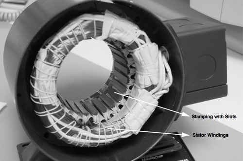
Because a BLDC motor dispenses with the brushes – instead employing an “electronic commutator” – the motor’s reliability and efficiency is improved by eliminating this source of wear and power loss. In addition, BLDC motors boast a number of other advantages over brush DC motors and induction motors, including better speed versus torque characteristics; faster dynamic response; noiseless operation; and higher speed ranges.1
Moreover, the ratio of torque delivered relative to the motor’s size is higher, making it a good choice for applications such as washing machines and EVs, where high power is needed but compactness and lightness are critical factors. (However, it should be noted that brush-type DC motors do have a higher starting torque.)
A BLDC motor is known as a “synchronous” type because the magnetic field generated by the stator and the rotor revolve at the same frequency. One benefit of this arrangement is that BLDC motors do not experience the “slip” typical of induction motors.
While the motors can come in one-, two-, or three-phase types, the latter is the most common type and is the version that will be discussed here.
The stator of a BLDC motor comprises steel laminations, slotted axially to accommodate an even number of windings along the inner periphery (Figure 1). While the BLDC motor stator resembles that of an induction motor, the windings are distributed differently.
The rotor is constructed from permanent magnets with two-to-eight N-S pole pairs. More magnet pairs increase torque and smooth out so-called torque ripple, evening the power delivery from the motor. The downside is a more complex control system, increased cost, and lower maximum speed.
Traditionally, ferrite magnets were used to make the permanent magnets, but contemporary units tend to use rare earth magnets. While these magnets are more expensive, they generate greater flux density, allowing the rotor to be made smaller for a given torque. The use of these powerful magnets is a key reason why BLDC motors deliver higher power than a brush-type DC motor of the same size.
Detailed information about the construction and operation of BLDC motors can be found in an interesting application note (AN885) released by Microchip Technology.2
Fundamentals of operation
The BLDC motor’s electronic commutator sequentially energizes the stator coils generating a rotating electric field that ‘drags’ the rotor around with it. N “electrical revolutions” equates to one mechanical revolution, where N is the number of magnet pairs.
For a three-phase motor, three Hall-effect sensors are embedded in the stator to indicate the relative positions of stator and rotor to the controller so that it can energize the windings in the correct sequence and at the correct time. The Hall sensors are usually mounted on the non-driving end of the unit (Figure 2).
Microchip Hall sensors
When the rotor magnetic poles pass the Hall sensors, a high (for one pole) or low (for the opposite pole) signal is generated. As discussed in detail below, the exact sequence of commutation can be determined by combining the signals from the three sensors.
All electric motors generate a voltage potential due to the movement of the windings through the associated magnetic field. This potential is known as an electromotive force (EMF) and, according to Lenz’s law, it gives rise to a current in the windings with a magnetic field that opposes the original change in magnetic flux. In simpler terms, this means the EMF tends to resist the rotation of the motor and is therefore referred to as “back” EMF. For a given motor of fixed magnetic flux and number of windings, the EMF is proportional to the angular velocity of the rotor.
But the back EMF, while adding some “drag” to the motor, can be used for an advantage. By monitoring the back EMF, a microcontroller can determine the relative positions of stator and rotor without the need for Hall-effect sensors. This simplifies motor construction, reducing its cost as well as eliminating the additional wiring and connections to the motor that would otherwise be needed to support the sensors. This improves reliability when dirt and humidity are present.
However, a stationary motor generates no back EMF, making it impossible for the microcontroller to determine the position of the motor parts at start-up. The solution is to start the motor in an open loop configuration until sufficient EMF is generated for the microcontroller to take over motor supervision. These so-called “sensorless” BLDC motors are gaining in popularity.
Controlling a BLDC motor
While BLDC motors are mechanically relatively simple, they do require sophisticated control electronics and regulated power supplies. The designer is faced with the challenge of dealing with a three-phase high-power system that demands precise control to run efficiently.
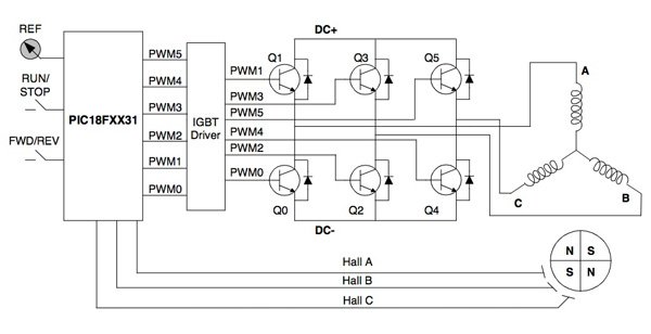
Figure 3 shows a typical arrangement for driving a BLDC motor with Hall-effect sensors. (The control of a sensorless BLDC motor using back EMF measurement will be covered in a future article.) This system shows the three coils of the motor arranged in a “Y” formation, a Microchip PIC18F2431 microcontroller, an insulated-gate bipolar transistor (IGBT) driver, and a three-phase inverter comprising six IGBTs (metal oxide semiconductor field effect transistors (MOSFETs) can also be used for the high-power switching). The output from the microcontroller (mirrored by the IGBT driver) comprises pulse width modulated (PWM) signals that determine the average voltage and average current to the coils (and hence motor speed and torque). The motor uses three Hall-effect sensors (A, B, and C) to indicate rotor position. The rotor itself uses two pairs of permanent magnets to generate the magnetic flux.
The system employs a six-step commutation sequence for each electrical revolution. Because the motor has two pairs of magnets, two electrical revolutions are required to spin the motor once.
Figure 4 shows the current flow in an identical arrangement of coils to the motor in Figure 3 (this time labeled U, V, and W) for each of the six steps, and Figure 5 shows the subsequent Hall-effect sensor outputs and coil voltages.
Figure 4: Coil-energizing sequence for one electrical revolution of a three-phase BLDC motor. (Courtesy of Atmel.)
A pair of Hall-effect sensors determines when the microcontroller energizes a coil. In this example, sensors H1 and H2 determine the switching of coil U. When H2 detects a N magnet pole, coil U is positively energized; when H1 detects a N magnet pole, coil U is switched open; when H2 detects a S magnet pole coil U is switched negative, and finally, when H1 detects a S magnet pole, coil U is again switched open. Similarly, sensors H2 and H3 determine the energizing of coil V, with H1 and H3 looking after coil W.
At each step, two phases are on with one phase feeding current to the motor, and the other providing a current return path. The other phase is open. The microcontroller controls which two of the switches in the three-phase inverter must be closed to positively or negatively energize the two active coils. For example, switching Q1 in Figure 3 positively energizes coil A and switching Q2 negatively energizes coil B to provide the return path. Coil C remains open.
Designers can experiment with 8-bit microcontroller-based development kits to try out control regimes before committing on the design of a full-size motor. For example, Atmel has produced an inexpensive starter kit, the ATAVRMC323, for BLDC motor control based on the ATxmega128A1 8-bit microcontroller.4 Several other vendors offer similar kits.
Driving a BLDC motor
While an 8-bit microcontroller allied to a three-phase inverter is a good start, it is not enough for a complete BLDC motor control system. To complete the job requires a regulated power supply to drive the IGBT or MOSFETs (the “IGBT Driver” shown in Figure 3). Fortunately, the job is made easier because several major semiconductor vendors have specially designed integrated driver chips for the job.
These devices typically comprise a step-down (“buck”) converter (to power the microcontroller and other system power requirements), gate driver control and fault handling, plus some timing and control logic. The DRV8301 three-phase pre-driver from Texas Instruments is a good example (Figure 6).
For more detail: An Introduction to Brushless DC Motor Control
- Why are BLDC motors becoming popular in automotive and HVAC sectors?
They eliminate mechanical commutators, improving reliability, durability, and allowing for smaller, lighter designs compared to traditional motors. - What component is needed to energize stator coils at the correct moment?
A microcontroller using input from position sensors is required to ensure precise timing for speed, torque control, and peak efficiency. - How does a BLDC motor differ from an induction motor regarding slip?
BLDC motors are synchronous types where the stator and rotor fields revolve at the same frequency, meaning they do not experience the slip typical of induction motors. - Can a BLDC motor operate without Hall-effect sensors?
Yes, sensorless versions use back EMF monitoring to determine rotor positions, though they require an open loop start-up configuration until sufficient EMF is generated. - What is the function of the three-phase inverter in the control circuit?
The inverter uses switches like IGBTs or MOSFETs to control which two phases are active to positively or negatively energize coils while keeping the third phase open. - How many electrical revolutions are required for one mechanical revolution if the motor has two magnet pairs?
Two electrical revolutions are required because N electrical revolutions equate to one mechanical revolution, where N is the number of magnet pairs. - What integrated chip example is provided for simplifying BLDC driver design?
The DRV8301 three-phase pre-driver from Texas Instruments is cited as an example that includes a buck converter, gate driver control, and fault handling. - What development kit is mentioned for experimenting with 8-bit microcontroller-based control?
The ATAVRMC323 starter kit by Atmel, based on the ATxmega128A1 microcontroller, is suggested for testing control regimes.