This time we will see how to measure AC voltage parameters with the help of micro-controller. First we will know about AC voltage parameters, then we will do the whole work step by step.
What is AC(Alternating Current):
“In alternating current (AC, also ac), the flow of electric charge periodically reverses direction. In direct current (DC, also dc), the flow of electric charge is only in one direction. The abbreviations AC and DC are often used to mean simply alternating and direct, as when they modify current or voltage.
AC is the form in which electric power is delivered to businesses and residences. The usual waveform of an AC power circuit is a sine wave. In certain applications, different waveforms are used, such as triangular or square waves. Audio and radio signals carried on electrical wires are also examples of alternating current. In these applications, an important goal is often the recovery of information encoded (or modulated) onto the AC signal.” _ from the wiki.
In Bangladesh, the alternating current of our supply line is of 220V AC and the line frequency is 50Hz.
So, we see that there are some parameters of AC voltage such as Peak Voltage, RMS Voltage, Line Frequency, Wave-shape, etc. In this project, we will not measure the Wave-shape, we will measure the peak voltage, RMS voltage, and line frequency to make the project easy and understandable.
What is Peak voltage:
The peak voltage is the Amplitude of the AC sine wave. If we see the wave-shape of our line voltage, we will see a pure sine wave like this:
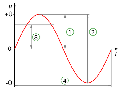
Fig: AC Sinusoidal Wave and its parameters.A sinusoidal curve
1 = Peak amplitude (\scriptstyle {\hat U}),
2 = Peak-to-peak amplitude (\scriptstyle 2{\hat U}),
3 = Root mean square amplitude (\scriptstyle {\hat U}/{\sqrt {2}}),
4 = Wave period (not an amplitude)
Peak-to-peak amplitude is the change between peak (highest amplitude value) and trough (lowest amplitude value, which can be negative) _wiki.
And the Peak amplitude is the half of the Peak-Peak Amplitude.
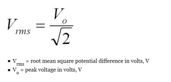
What is RMS (Root Mean Square) Amplitude:
The RMS value represents the effective value of the AC(Alternating Current). There is a relation between Peak Voltage and RMS Voltage.
So we have a clear idea about Peak-Peak Voltage and RMS voltage by now. Now we’ll see another term “Line Frequency”.
What is Frequency:
Frequency is the number of occurrences of a repeating event per unit time . _wiki
To know more, read the wiki page about Frequency.
Now lets do some works. We need to measure all these parameters with the help of micro-controller. In this project, we will need some materials listed below:
a. Micro-Controller PIC16F73 1 pcs
b. LCD Display 16X2 – 1pcs
c. Voltage Regulator L7805 – 1pcs
d. Transformer 220:12 – 1pcs
e. Capacitors 1000uF/25V – 2pcs, 0.1uF – 1pcs
f. Diode 1N4007 – 5pcs
g. Resistors: 10K,100K,1K, Variable-10K – as required.
h. Crystal 8MHz – 1pcs
i. LED – 1 pcs any color
j. Others.
And the software we will use:
a. MicroC pro for PIC – as compiler
b. Proteus ISIS – as simulator
c. Sprintlayout 5.0 – as PCB designing
Circuit Diagram:
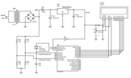
Circuit Details:
Line voltage is converter to 12V AC with a 220:12 Transformer (TR1) and then with the help of 4 Diodes (1N4007) that AC is converted into pulsating DC. And again another Diode is used to convert the pulsating DC into pure DC with a Capacitor (1000uF/25V). L7805 voltage regulator is used to get a fixed voltage (+5V DC). This 5V DC will be used to run the Micro-controller and LCD Display. With LCD Display there is a Variable Resistor used to set the contrast of the LCD Display. In the back again, two voltage divider is used to measure the AC parameters. One Diver between them is with 10KΩ and 1KΩ. This divider is used to measure the peak point the the sine wave. Also a 0.1uF non-polar ceramic capacitor is used with this divider to reduce noise (if any). This divider is fed to the ADC of the micro-controller(we’ll see it later). And another voltage divider is using 100KΩ & 100KΩ and the divider is fed to a pin named TOCKI (Timer 0 Clock Input). This pin is used to measure the frequency with the help of Timer module of the micro-controller (PIC16F73). Also there is another device in our circuit, Crystal. Its like an oscillator that will produce clock pulse for the micro-controller.
Circuit Operation:
The line voltage is converter into a low voltage AC with the transformer 220:12. And the that AC is rectified with a bridge diode. This will create a pulsating DC signal. This signal is fed to the ADC of the micro-controller to measure the amplitude of the voltage. As the voltage is divided with voltage divider circuit so the calculation for the line voltage measurement will be:
Line Voltage = {((10KΩ + 1KΩ)/1KΩ) x Voltage in the PIN }x (220/12);
So the main work will be to find the voltage in the PIN of the micro-controller. Now this voltage is measured with the help of micro-controller and it is displayed in the LCD display. This voltage is the peak amplitude. And the RMS vale will be,
RMS Value = peak voltage x √2;
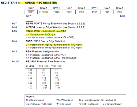
This value is also displayed on the LCD. Now the line frequency. There is another voltage divider with two 100KΩ resistors. This is an interesting section. The micro-controller have a module Time0 inside. And there is an option to use this module as a counter. This is set by the register OPTION_Reg.
And the as we are measuring just after the bridge rectifier so the frequency will be double of the line frequency. When we’ll measure the line frequency, we’ll divide the result by 2 to get the actual result.
The Program:
In the program, we’ll use microCpro as our compiler. Here is the program:
/*******************************************************************************
Program for Power Factor measurement
MCU: PIC16F73  X-Tal: 8MHz
Program Written By Engr. Mithun K. Das; Email: [email protected]
*******************************************************************************/
unsigned char ch;
unsigned int adc_rd0;
unsigned int temp0=0,temp1=0;
unsigned max_point0 = 0;
unsigned int i,tlong0,tlong1;

// LCD module connections
sbit LCD_RS at RB7_bit;
sbit LCD_EN at RB6_bit;
sbit LCD_D4 at RB5_bit;
sbit LCD_D5 at RB4_bit;
sbit LCD_D6 at RB3_bit;
sbit LCD_D7 at RB2_bit;

sbit LCD_RS_Direction at TRISB7_bit;
sbit LCD_EN_Direction at TRISB6_bit;
sbit LCD_D4_Direction at TRISB5_bit;
sbit LCD_D5_Direction at TRISB4_bit;
sbit LCD_D6_Direction at TRISB3_bit;
sbit LCD_D7_Direction at TRISB2_bit;
// End LCD module connections

char message1[] = "PK:000V";
char message2[] = "RMS:000V";

char *freq = " 00";
void Display_Freq(unsigned int freq2write)
{
 freq[1] = (freq2write/10) + 48;    // Extract tens digit
 freq[2] =  (freq2write/1)%10 + 48;    // Extract ones digit
 // Display Frequency on LCD
 Lcd_Out(2, 11, freq);
 Lcd_Out(2,14,"Hz");
}
void main()
{
 TRISA = 0xFF; // set all pins of PORT A as input
 TRISC = 0x00; // set all pins as output
 PORTC = 0x00; // clear port C
 PORTB = 0x00; // clear port B
 ADCON1=0x00; // set all Analog
 Delay_ms(1000);

 OPTION_REG = 0b00101000; // set TOCKI as clock counter

 Lcd_Init();
 Lcd_Cmd(_LCD_CLEAR);
 Lcd_Cmd(_LCD_CURSOR_OFF);

 Lcd_Out(1,1,"Measurement of");
 Lcd_Out(2,1,"AC parameter ");
 Delay_ms(2000);

 Lcd_Cmd(_LCD_CLEAR);

  while(1)
  {
            // Find the peak amplitude of the sine wave...
            max_point0 = 0;
            for(i=0;i<5000;i++)
            {
                ADCON0 = 0b00000001;
                if(temp0 = ADC_Read(0),temp0>max_point0)
                {
                   max_point0 = temp0;
                }
                Delay_us(5);
            }

               max_point0 = abs(ceil((long)max_point0));

               tlong0 = (long)max_point0*(5/255)*11*220/12; // find the peak amplitude of the line
               tlong1 = (long)max_point0*((5/255)*11*220/12)*0.707; // find the rms value of the line voltage

            message1[3] = tlong0/100 + 48; // convert into ASCII
            message1[4] = (tlong0/10)%10 +48; // convert into ASCII
            message1[5] = (tlong0)%10 +48; // convert into ASCII
            Lcd_Out(1,1,message1); // Display message on LCD

            RC0_bit = ~RC0_bit;

            message2[4] = tlong1/100 + 48;  // convert into ASCII
            message2[5] = (tlong1/10)%10 +48;  // convert into ASCII
            message2[6] = (tlong1)%10 +48;  // convert into ASCII
            Lcd_Out(1,9,message2);  // Display message on LCD

            TMR0=0; // clear TMR0
            Delay_ms(1000);  // Delay 1 Sec
            Lcd_Out(2,1,"FREQUENCY:");
            Display_Freq(TMR0/2); // divide by 2
            TMR0=0;

  }// while
}// void main
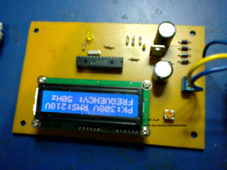
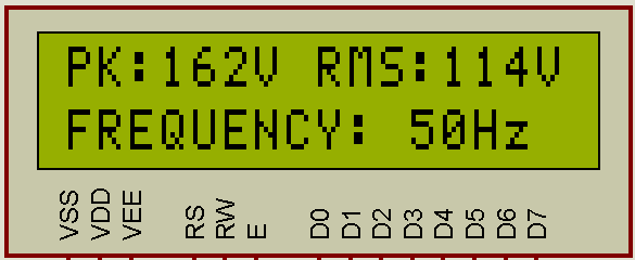
And the simulation result of our project is:
And the developed system is here: