


Summary of A DCF77 Clock with RS232 Interface using PIC16F84
Summary: A DCF77-synchronized clock uses a PIC16F84 microcontroller to drive a 6-digit multiplexed 7-segment display with automatic brightness control via a photocell and PWM-like timing. It includes an RS232 interface implemented with bit-banged serial on the PIC and a MAX232 level shifter, and a separate U4224B-based radio receiver module with ferrite antenna for DCF77 demodulation.Parts used in the DCF77 Clock with RS232 Interface using PIC16F84:
- PIC16F84 microcontroller
- 6 x 7-segment LED displays
- 74138 decoder
- 74247 BCD-to-7-segment driver
- Transistors for segment/coil driving
- Photocell A1060
- Capacitor for PWM timing
- MAX232 level shifter
- U4224B demodulator (TEMIC Semiconductors)
- Ferrite antenna
- Separate enclosure/box for receiver and antenna
Description:
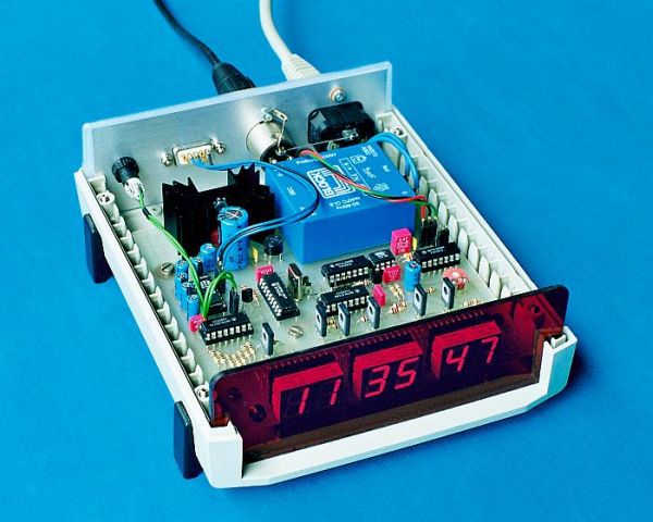
The clock is synchronised via the German time signal DCF77. It has a display with automatic brightness control and a RS232 computer interface.
Design Overview:
The clock is built around a PIC16F84 microcontroller from Microchip. I chose this microcontroller since its FLASH memory is easy to program and assembler and programmer software is freely available for GNU/Linux. It has 13 general input/output pins which is just enough to implement all the feature I wanted.
- Display with Brightness ControlThe 6 7-segment LEDs are multiplexed with a frequency of 100 Hz. A simple combination of a 74138, 74247 and some transistors is used. With more I/O pins on the microcontroller, one could save the two chips but the current might be to high for a microcontroller.
The brightness of the LEDs is controlled by the ambient light. This is achieved by varying their illumination time, also known as Pulse Width Modulation. Whenever a new 7-segment LED is switched on, a capacitor is discharged. The capacitor is then slowly charged. When the voltage at the capacitor gets higher than the reference voltage determined by the A1060 photocell, the display is blacked out.
- RS232 InterfaceThe hardware part of the RS232 interface is straightforward. Two pins of the PIC16F84 act as RX/TX, and MAX232 does the conversion from TTL to RS232 signal level.
The software part is more interesting. Since the PIC16F84 does not have an USART, the coding and decoding of the serial signal is entirely done in software. This is suboptimal since the PIC16F84 does not have interrupts for any I/O pins, so the software must constantly poll the RX pin. You can get example code from Mircochip for this. But as a consequence, the main code for analysing the radio signal and driving the display is called from the RS232 code and is only allowed to use a limited amount of time. This amount of time available decreases with higher serial speeds, so the highest possible speed with this design is 1200 Baud. Next time I would definitely use a microcontroller with a build in USART.
- Radio Signal ReceiverThe radio signal is demodulated with an U4224B by TEMIC Semiconductors. The digitised serial signal is displayed by a LED and fed into to PIC16F84. The U4224B together with the ferrite antenna are placed in a separate box to keep circuit noise emission from the antenna and to allow perfect alignment of the antenna.
For more detail: A DCF77 Clock with RS232 Interface using PIC16F84
- What microcontroller is used in the project?
The project uses a PIC16F84 microcontroller. - How is the display brightness controlled?
Brightness is controlled by varying display illumination time using a capacitor and an A1060 photocell to determine reference voltage. - How are the 7-segment LEDs multiplexed?
The six 7-segment LEDs are multiplexed at 100 Hz using a combination of a 74138, 74247 and transistors. - What handles TTL to RS232 level conversion?
MAX232 performs the conversion from TTL to RS232 signal levels. - Does the PIC16F84 have a hardware USART?
No, the PIC16F84 does not have a hardware USART; serial is implemented in software. - What is the maximum serial speed achievable with this design?
The highest possible serial speed with this design is 1200 Baud. - How is the DCF77 radio signal demodulated?
The radio signal is demodulated using a U4224B demodulator from TEMIC Semiconductors. - Why is the receiver and antenna placed in a separate box?
They are placed in a separate box to reduce circuit noise emission from the antenna and allow precise antenna alignment.
Related projects
PIC Stepper Motor Controller using PIC16F84A with Proteus Simulation
Introduction Stepper motors are widely used in embedded systems and DIY electronics projects where precise position control is required. This PIC Stepper...
Programmers & ICSP · PIC16F84APIC Musical Doorbell using PIC16F84A with Proteus Simulation
IntroductionThis microcontroller project demonstrates a musical doorbell built around a PIC16F84A and a simple piezo sounder.Using two push buttons, the system allows...
Beginner Tutorials · PIC16C84Exploring the World of PIC Microcontrollers: An Architectural Overview
A Peripheral Interface Microcontroller (PIC), developed by General Instruments Microcontrollers in 1993, operates under software control and is programmed to execute various...
Clocks & TimersAdaptive Alarm Clock: Build a Smart, User-Centric wake-Up system
Project Overview The goal of this ambitious undergraduate project was to develop a novel alarm clock capable of analyzing a person's unique...
Clocks & TimersDesigning Your Ideal Alarm Clock: An Introduction to PIC18
Within this laboratory session, you'll employ the C language to create an alarm clock, delving into the implementation of "C" programs on...
Clocks & TimersBuilding your Dream Alarm Clock Using the PIC18
Objective: In this laboratory session, your objective is to create an alarm clock using the C programming language. You will gain proficiency...

Ibrar Ayyub
I am an experienced technical writer holding a Master's degree in computer science from BZU Multan, Pakistan University. With a background spanning various industries, particularly in home automation and engineering, I have honed my skills in crafting clear and concise content. Proficient in leveraging infographics and diagrams, I strive to simplify complex concepts for readers. My strength lies in thorough...