
Summary of Telephone operated remote control using PIC16F84A microcontroller
This article details a telephone-operated remote control project using a PIC16F84A microcontroller. It uniquely activates devices based on ring counts without answering the call, avoiding charges. The system uses DIP switches to configure activation rings and delays, allowing up to 8 relays to be controlled via specific ring patterns after an initial trigger sequence.
Parts used in the Telephone operated remote switch:
- PIC16F84A microcontroller
- 18pin sockets (base)
- DIP SWITCH
- Relays
- Phone line interface
- Power supply
- HT-Soft PIC C compiler
- Compiler Hex code file
This design controls up to 8 devices using a PIC microcontroller (PIC16F84A) connected to the phone line. The unique feature here is that unlike other telephone line based remote control, this device does not need the call to be answered at the remote end so the call will not be charged. This device depends on number of rings given on the telephone line to activate/deactivate devices.
1. Circuit diagram (designed by www.tronicszone.com)
2. Parts List
3. C source code complied using HT-Soft PIC C compiler
4. Compiler Hex code file to be directly programmed into the PIC
Instructions for the telephone operated remote switch:
A) While constructing the main circuit, make sure you use 18pin sockets (base) for the PIC16F84A. Do not solder the IC directly to the board since you may have to remove it for programming. Before you use the PIC on the main circuit, you have to first program it.
B) To program the PIC16F84A microcontroller:
There are lots of programmers on the Internet available to program PIC microncontrollers. Given below are links to some free PIC programmer hardware/software:
- http://www.covingtoninnovations.com/noppp/
- http://www.picallw.com/
- http://www.lpilsley.uklinux.net/software.htm
Note: Programm the chip with the hex file attached above and remember to set the fuse bits to use “EXTERNAL HS OSCILLATOR” mode!
C) Remove the PIC from the programmer socket and put it into the main circuit socket.
Set the DIP SWITCH as follows:
Switch3 Switch4 No. of initial rings to Switch ON(activate half of the board)
OFF OFF 5
ON OFF 4
OFF ON 3
ON ON 2
The number of initial rings to Switch OFF is one more than the number of rings to switch ON. For example, if you have set switch3 OFF & Switch4 ON then number of initial rings to activate half of the board to switch ON the relays is 3 and number of initial rings to activate half of the board to switch OFF the relays is 3+1 = 4
Switch1 Swtich2 Delay before making the second set of rings
OFF OFF 20sec
ON OFF 15sec
OFF ON 10sec
ON ON 5sec
This is the maximum delay the board can take after it is half activated. It will reset after this delay.
D) Now connect the circuit to the phone line and switch on its power supply.
E) You can test the board now. For example set the DIP switch to Switch1 ON, Switch2 OFF (15 sec delay) & switch3 ON, switch4 OFF (4 rings to activate half for switching ON). If you want to switch ON relay 1 (connected to RB0 of main circuit) then you have to do the following:
1. Give 4 rings and put down the receiver
2. Wait 5 seconds (this 5 seconds wait is required to prevent the board from detecting continous rings)
3. then within 15 seconds give 1 ring (1 ring for relay1, 2 rings for relay2 and so on) and put down the receiver
4. then within 5 sec the relay1 will switch ON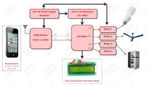
To switch off relay1:
1.Give 5 rings and put down the receiver
2.Wait 5 seconds (this 5 seconds wait is required to prevent the board from detecting continous rings)
3.then within 15 seconds give 1 ring (1 ring for relay1, 2 rings for relay2 and so on) and put down the receiver
4.then within 5 sec the relay1 will switch OFF
IMPORTANT: This circuit has been tested by me and found to work correctly. I cannot guarantee that the circuit will work at your end since it depends on error free construction and usage. Please do not contact for any support and requests, any such requests will not be entertained.
For more detail: Telephone operated remote control using PIC16F84A microcontroller
- How does this device avoid call charges?
The device does not require the call to be answered at the remote end; it activates based on the number of rings. - Can I solder the PIC16F84A directly to the board?
No, you must use an 18pin socket because you may need to remove the IC for programming. - What fuse bits setting is required for the PIC?
You must set the fuse bits to use EXTERNAL HS OSCILLATOR mode. - How do I calculate the rings needed to switch off the relays?
The number of initial rings to switch OFF is one more than the number of rings set to switch ON. - What is the maximum delay the board can take after half activation?
The maximum delay is 20 seconds, after which the board will reset. - Why is there a 5-second wait required during testing?
This wait prevents the board from detecting continuous rings. - Does the author guarantee the circuit will work for everyone?
No, the author states they cannot guarantee the circuit will work as it depends on error-free construction and usage. - How many devices can this design control?
This design controls up to 8 devices using the PIC microcontroller.
