Summary of PIC 12F675 Microcontroller Tutorial.
Summary (under 100 words): A beginner tutorial for the PIC 12F675 microcontroller covering its features (8‑pin package, 4MHz internal oscillator, 10‑bit ADC, timers, 1K program words, 64B RAM, 128B EEPROM), ICSP programming with ICPROG, power supply recommendations, oscillator calibration, oscillator modes, and a first project: an LED flasher. Includes circuit/build tips, source/hex availability, and brief C examples showing TRISIO and GPIO usage.
Parts used in the 12F675 LED Flasher Project:
- PIC12F675 microcontroller (8‑pin)
- Solderless breadboard
- LED
- Current limiting resistor (1k recommended, 220R optional)
- 10uF electrolytic capacitor (voltage rating > your max input, e.g., >35V)
- 5V regulator 7805
- Wall DC power supply or 9V battery (input >8V and <=35V for regulator)
- ICSP programmer with ICSP connector (4‑pin molex recommended)
- Connecting wires
 12F675
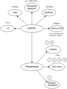
The 12F675 microcontroller is packaged in an 8 pin chip and even though it is tiny it is packed with peripherals. It even has a 10bit ADC built in (this is the same ADC that you can find on the 16F877A and 16F88 used elsewhere on this site). So learning about this peripheral is also useful for these other parts. The 12F675 has 1024 words of program memory, 64 Bytes of RAM and 128 Bytes of EEPROM, an internal oscillator, timers an ADC and a comparator.
12F675 Microcontroller Features
The following bubble diagram shows the major peripherals and features of the 12F675 in a visual format:
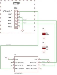
12F675 Microcontroller Programming
You can program the microcontroller using an ICSP programmer (you can use it for any PIC chip). ICSP connections are shown in the diagram below.
To use it you will need software running on the PC : ICPROG. This lets you flash the hex file generated by the compiler into the 12F675
You can find a programmer circuit here and information on using ICPROG here.
12F675 : ICSP connections:
12F675 pinouts
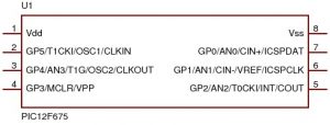
Other views:

12F675 Microcontroller Power Supply
If you don’t have a bench power supply then you should use the following standard circuit.
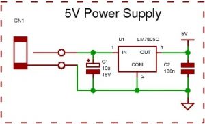
All you will need is a wall power supply block with dc output (greater than 8V and no more than 35V) or a 9V battery to plug into CN1.
Note: It is best to use the 5V power supply circuit as it not only correctly regulates the dc voltage but it protects your PIC chip. The input voltage can go up to 35V without damaging the 7805.
You would not want to use that high voltage for very long if using reasonable current as the 7805 would have to get rid of the excess power as heat. Say you used 100mA dropping 35V to 5V gives P=VxI = 30 *0.1 = 3W – a huge power output – the 7805 would get very hot and go into thermal shutdown!

12F675 oscillator calibration value.
Before Programming it with your hex file make a note of the oscillator calibration value which is factory set by Microchip.
Note:The calibration value is located at the last memory address 0x3FF
This value calibrates the 4MHz oscillator to 1%. If overwritten you have to re-calculate it yourself. Click here for m ore detailed information (in a further tutorial) and then come back here.
If you use ICPROG then it warns you that you are about to overwrite the oscillator calibration value and asks if you use the value from the hex file – you should answer No to keep the original value.
Note: Each oscillator calibration value will be different so you have to note down each value for each chip and not muddle them up! If you loose it you can recalculate it but you will need a frequency counter.
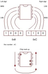
Tip for storing the calibration value
This is a tip I have seen on the web for storing your calibration value on the device itself – it’s so good I thought I would include it here.
All you do is think of the pins of the 8 pin device as a binary number and mark those pins with the value you read out using the programmer (in read mode)
All you need is the last hex number as the 1st is always 34.
So lets say you read your device and get 348C. Just use the 8C part.
Oscillator modes
As with the 16F88 the 12F675 microcontroller has eight oscillator modes but unlike the 16F88 the internal oscillator is fixed at 4Mhz.
You can use an external oscillator either a resistor capacitor pair, an external clock signal or a crystal (or resonator). You can even operate the crystal to 20Mhz if you need extra performance.
Note: Only use the external modes if absolutely necessary as you loose the use of pins (loosing 2 out of 6 I/O pins is a lot to loose).
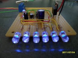
Tutorial 1 : 12F675 Flashing an LED
The first program is a flashing LED – it always is! The reason is that there is the least hardware to go wrong so it gives a good test of your system setup.
This project also uses the 12F675’s internal oscillator and you don’t need a crystal so there is even less to go wrong!
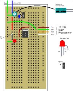
Use the solderless breadboard to construct the following circuit:
Note: Double check your connections on the breadboard.
Note: the plus sign on the 10u electrolytic capacitor which must connect to the positive input voltage and have a voltage rating stamped on it of greater than 35V (or greater than your maximum dc power block output). The LED must be connected with the flat side to ground.
Solderless breadboard layout
Circuit diagram
The following diagram shows the above Plugblock circuit in schematic form. It is exactly the same circuit but lets you view the circuit in an easier way and shows the layout of the circuit from the point of view of the circuit block functions rather than how you have to place the components (using the Plugblock).
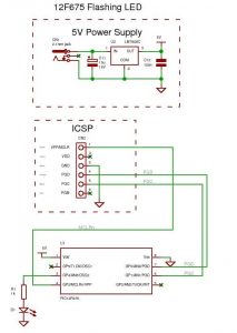
Note: The LED current limiter resistor (1k) is not the ideal one it just lets you see the led (you don’t need the maximum current to see the light from the LED) – to use the LED at higher output replace it with 220R. This gives lots more current so it is brighter I=(5-2)/220=13mA (most leds let you use 20mA but you would have to check the forward diode drop, here assumed as 2V, to get the exact resistor. It’s only an LED I always assume 2V as the slight variations for different colored LEDs won’t make much difference.
Read 12F765
Using ICPROG (you can find a description of how to use it here) set the device to 12F675 and hit the read button. Remember to note down the contents of address 0x3FF.
Software
The next thing to do is to flash the LED to prove that the system you have is working as reading back data is not very interesting.
To get the file software project files and c source code click here.
You can use the hex file directly to program the 12F675 then it will flash the led on and off or you can re-compile the files using the free compiler from Mikroelectronika. You can find a very brief compiler tutorial here.
Some of the C source code is :
void init_ports(void) {
TRISIO = 0; // set as output
}
//////////////////////////////////////////////////////////////////////
// Start here
void main() {
init_ports();
while(1) { // infinite loop
GPIO = (1<<4);
delay_ms(200);
GPIO = 0;
delay_ms(200);
}
}
As you can see main() is a very simple easily readable program the only slightly non obvious part is the (1<<4) statement.
This just takes the value 1 and bit shifts it left four times so the number 4 is the same as bit position 4. Bits in a byte are labeled 7 to 0 from left to right and (1<<0)=1, (1<<1)=2, (1<<2)=4, (1<<3)=8 etc. so this gives an easy way of setting an individual bit in a byte that is also easy to read. If you wanted to set bit 5 you could write GPIO = 32; (or 0x20 in hex) but GPIO = (1<<5) is much easier to read.
Note: The C programming course has more on PORT control techniques.
Try changing the delay time (in both delay_ms statements) to a smaller or larger value and re-compile and re-flash the chip to see the effect.
- What do I need to program the 12F675?
You need an ICSP programmer with an ICSP output connector and software such as ICPROG to flash the hex file. - Can I use the provided hex files without installing a compiler?
Yes, the downloadable zip file contains hex files so you do not have to install the compiler. - Does the 12F675 have an internal oscillator?
Yes, it has an internal oscillator fixed at 4MHz. - How should I handle the oscillator calibration value before programming?
Read and note the calibration value at address 0x3FF and answer No in ICPROG when asked to overwrite it. - What power supply is recommended for the 12F675 projects?
Use a 5V regulated supply built with a 7805 and a wall DC block or 9V battery as input; input can be up to 35V to the 7805. - What is the simplest first project in the tutorial?
The first project is a flashing LED using the internal oscillator on a solderless breadboard. - How do I set GPIO pins as outputs in the example code?
The example sets TRISIO = 0 to configure all GPIO pins as outputs. - How is a single GPIO bit set in the example code?
The code uses bit shifting, for example GPIO = (1 << 4) to set bit 4. - Do I need to remove the ICSP connector after programming?
Sometimes yes; the programmer may not release Vpp or you may need to access ICSP pins for analog readings.