
Summary of Using Digole 12864ZW LCD with PIC18F
Digole 12864ZW is a 128×64 graphic LCD based on the ST7920. The article explains wiring the 20-pin module, enabling graphics using an 8-bit parallel interface (PSB to Vdd, RST to Vdd), and adapting Microchip XLCD library (modify XLCDInit) to initialize the display in graphic mode. Drawing requires setting pixel addresses with two XLCDCommand calls and writing pixel data with two XLCDPut calls. The display addresses pixels in horizontal groups of 16 and values in groups of 8, yielding an 8×16 horizontal map across 64 lines for full 128×64 resolution.
Parts used in the Digole 12864ZW Project:
- Digole 12864ZW 128×64 graphic LCD module
- PIC microcontroller (example: PIC18F)
- Microchip XLCD library (XLCD.h, XLCD.c, XLCD.def)
- Wiring/connector for 20-pin module
- 10k variable resistor (for contrast to V0)
- Power supply (Vdd and Vss)
- Jumper J1 on the LCD module
- Optional reset wiring (RST to Vdd or controlled by MCU)
Digole 12864ZW is a 128×64 pixels graphic LCD that can be found at attractive prices and this is why it started appearing in projects across the web. It is based on ST7920 chip which is not so well known and to me it wasn’t the easiest to work with.’
The documentation for this display can be found here. You can find a couple of examples on how to use this display and some attempts on making a library and most of this information is for interfacing with arduino. For PIC interfacing i couldn’t find much info.
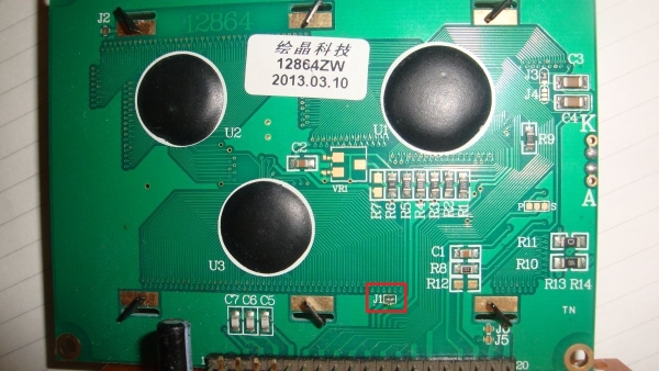
The module has a 20 pin connection, each described below. Vout i havent used and left it unconnected. For contrast you can use V0 (pin 3) by connecting it to Vdd through a 10k variable resistor. However to get it to work you will need to enable jumper J1 from the back of the module as in figure 1.
| Pin # | Function |
| 1 | Vss |
| 2 | Vdd |
| 3 | V0 |
| 4 | RS |
| 5 | RW |
| 6 | EN |
| 7 | DB0 |
| 8 | DB1 |
| 9 | DB2 |
| 10 | DB3 |
| 11 | DB4 |
| 12 | DB5 |
| 13 | DB6 |
| 14 | DB7 |
| 15 | PSB |
| 16 | NC |
| 17 | RST |
| 18 | VOUT |
| 19 | BLA |
| 20 | BLK |
As per the datasheet the display can be used in many ways and this is a strong feature. I used it the traditional way 8 bits parallel. For this, PSB pin must be connected to Vdd, i also connected RST pin to Vdd as i will reset the display in software. The rest of the connections are the same as with any 16×2 alphanumeric displays.
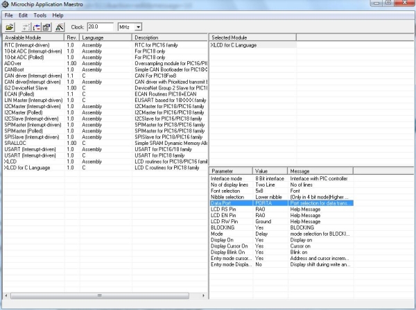
Microchip XLCD library is a great starting point to using the Digole 12864ZW with a PIC microcontroller. I used Application Maestro to set up the library. As mentioned we will use 8 bits interface in delay mode. Set the ports and pins and the rest doesn’t really matter.
Once done pressing Ctrl+G will generate the library files to be included in your project. You will need the XLCD.h, XLCD.c and XLCD.def. Now this Digole display can run in text mode with this library with major issues.To get to each line though you will need to go to specific addresses.
To use the LCD in graphic mode we will need to change the XLCDinit function in XLCD.c file.
void XLCDInit(void){_vXLCDreg=1;
XLCD_DATAPORT_TRIS = 0x00;
XLCD_DATAPORT = 0;
XLCD_RSPIN_TRIS =0;
XLCD_ENPIN_TRIS =0;
XLCD_RWPIN_TRIS =0;
XLCD_RSPIN =0;
XLCD_ENPIN =0;
XLCD_RWPIN=0;
XLCDDelay15ms();
XLCD_DATAPORT = 0b00110000;
XLCDDelay4ms();
XLCD_DATAPORT = 0b00110000;
XLCDDelay4ms();
XLCDCommand(0x0C);
XLCDDelaylcd();
XLCDCommand(0x01);
XLCDDelay15ms();
XLCDCommand(0x06);
XLCDDelaylcd();
XLCDCommand(0x34);
XLCDDelay15ms();
XLCDCommand(0x36);
XLCDDelay15ms();
_vXLCDreg=0;return;}
 The other two functions we will use from the XLCD library are XLCDCommand and XLCDPut, which are used to pass a command to the display and a value respectively. Using these functions you don’t have to worry about controlling RS , RW and EN.
After calling the XLCDinit() function in main() you have now setup the display in graphic mode. To start drawing you need first 2 XLCDCommand instructions that set the pixel address and then 2 XLCDPut instructions to draw the pixels.
In figure 3 you can see the address map of Digole 12864ZW in the operating mode described above. It can be observed the horizontally you cannot address pixels individually but in groups of 16 and values you can write in groups of 8. The 1st byte represents the byte in the first XLCDPut instruction and the 2nd byte the value in the 2nd instruction. You cannot make 1 byte to start at the middle of the address location. We have 8 addresses of 16 pixels each horizontally 8×16=128 pixels and 64 lines =>128×64 resolution.
For more detail: Using Digole 12864ZW LCD with PIC18F
- How is the Digole 12864ZW LCD interfaced in the article?
It is interfaced using an 8-bit parallel mode with PSB tied to Vdd and RST tied to Vdd for software reset. - Can the Microchip XLCD library be used with the Digole 12864ZW?
Yes, the article uses the Microchip XLCD library and generates XLCD.h, XLCD.c, and XLCD.def via Application Maestro. - What must be changed to run the LCD in graphic mode?
The XLCDInit function in XLCD.c must be modified as shown in the article to initialize the display in graphic mode. - How do you draw pixels on the display?
Call two XLCDCommand instructions to set the pixel address, then use two XLCDPut instructions to write the pixel data. - How is pixel addressing organized on this display?
Pixels are addressed horizontally in groups of 16 and values are written in groups of 8; there are 8 horizontal addresses of 16 pixels across 64 lines. - What pin is used for contrast adjustment?
Pin 3 (V0) is used for contrast and can be connected to Vdd via a 10k variable resistor. - Do you need to enable any jumper on the module?
Yes, jumper J1 on the back of the module must be enabled for proper operation as mentioned in the article. - Which pins control data and commands when using XLCD functions?
XLCDCommand and XLCDPut handle RS, RW, and EN control, so you do not need to manage those signals manually when using those functions.
