Summary of Photomultiplier Tube (PMT) Controller Circuit B using pic-microcontrolleroard
This article describes a four-channel PMT controller system based on a PIC microcontroller. It manages high voltage levels, offset voltages, amplifier gain, and channel mixing via USB or RS-232. The system identifies connected PMT modules using an interface board with analog ID signals. Additionally, it features a USB-based scan controller circuit that drives X-Y scanner galvos and generates timing signals for data acquisition.
Parts used in the Four Channel PMT Controller:
- PIC microcontroller
- USB connection (HID device)
- PIC-to-PIC RS-232 protocol link
- Hand unit
- PMT Interface Board
- External amplifier system
- X-Y scanner galvos
- Scan Controller Circuit Board
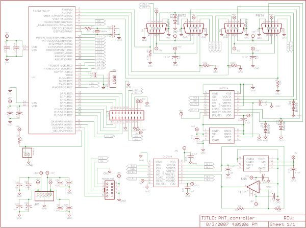
The four channel PMT controller board is a PIC microcontroller based device that communicates with a PC by USB as an HID device and with a PIC-based “hand unit” via PIC-to-PIC RS-232 protocol. These two external inputs (USB and RS-232) send strings to the PMT controller that:
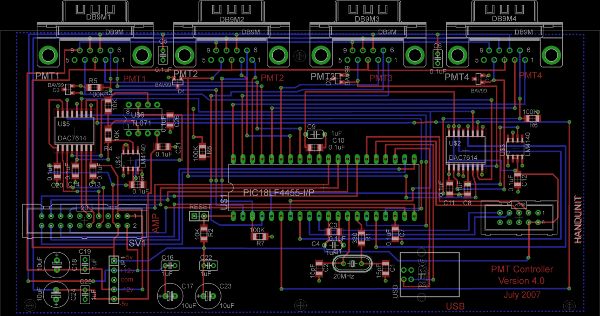
- Sets the four high voltage levels of the PMTs
- Provide four bipolar offset voltages for black level adjustment on an external amplifier system
- Control a 2 level programmable gain of a four channel external amplifier system
- Control analog mixing of channels of the four channel external amplifier system
- Depending on the type of PMT module attached, communicate with it (Circuit board specification)
Figures 1 and 2 show the current printed circuit board and schematic layouts.
PMT Interface Board
The PMT Interface Board is used to indicate to the controller which type of PMT is connected on each channel. The type of PMT is specified using an analog ID signal. The PMTs that can currently be recognized by the system are:
- HC125 Bialkali module
- Ultra Bialkali (UBA) module
- H7422P-40MOD Type 1 (with cooler and protection circuit)
- H7442P-40MOD Type2 (without cooler and protection circuit)
- GaAsP hybrid detector
(See the PMT controller specification for more information about the analog ID codes)
Figures 3 and 4 show the printed circuit board and schematic layouts for the interface board.
Scan Controller Circuit Board – USB based scancard
Our simplest scan controller is an independent board that communicates with the PC via USB connection. It drives the X-Y scanner galvos and produces the timing signal for data acquisition. Figures 5 and 6 show the printed circuit board and schematic layouts. It has several unique features such as a zero-latency gate
For more detail:Photomultiplier Tube (PMT) Controller Circuit B
- How does the PMT controller communicate with a PC?
The controller communicates with a PC by USB as an HID device. - What types of PMTs can be recognized by the system?
The system recognizes HC125 Bialkali, Ultra Bialkali, H7422P-40MOD Type 1, H7442P-40MOD Type 2, and GaAsP hybrid detector modules. - How is the type of PMT specified to the controller?
The type of PMT is specified using an analog ID signal on the PMT Interface Board. - What functions do the external inputs send to the PMT controller?
Inputs set high voltage levels, provide bipolar offset voltages, control programmable gain, and manage analog mixing of channels. - What is the role of the Scan Controller Circuit Board?
It drives the X-Y scanner galvos and produces the timing signal for data acquisition. - Does the scan controller have unique features?
Yes, it features a zero-latency gate. - Can the controller control a four channel external amplifier system?
Yes, it controls a 2 level programmable gain and analog mixing of channels. - What protocol is used for communication between the controller and the hand unit?
A PIC-to-PIC RS-232 protocol is used for this communication.