Summary of A digital thermometer or talk I2C to your atmel microcontroller using pic microcontroller
The article explains using an Atmega8 microcontroller to communicate with a Linux PC via RS232 without a MAX232 chip by bit-banging the I2C/TWI protocol over the PC serial port. It outlines I2C basics (SDA/SCL, start/stop, addressing, ack bits), advantages of I2C for small data transfers, and the plan to implement I2C in user space to build a thermometer example, with a follow-up adding an LCD.
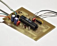
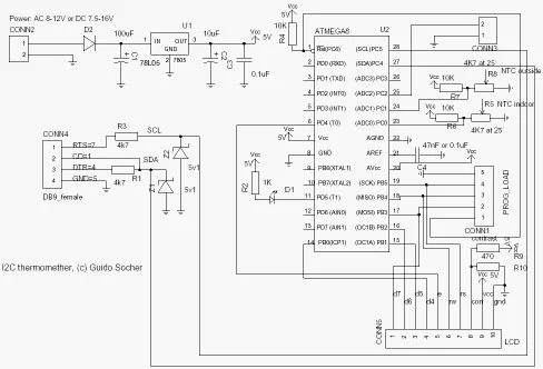
Parts used in the Thermometer/I2C over RS232 Project:
- Atmega8 microcontroller
- Linux PC with RS232 serial port
- RS232 physical connection (serial cable)
- Pull-up resistors (4.7K) for SDA and SCL
- Power supply for each device (5V for 5V ICs)
- Temperature sensor (for the thermometer example)
- GCC AVR programming environment (toolchain)
Abstract:
The Atmega8 microcontroller from Atmel has plenty of digital and analog input/output lines. It is the ideal device to develop any kind of measurement equipment.
In this article we see how to interconnect the microcontroller to a linux PC over a physical RS232 interface without the extra MAX232 chip.
Introduction
A pre-requisite for this article is that you have the GCC AVR programming environment installed as described in my “Programming the AVR microcontroller with GCC, libc 1.0.4” article. If you want to avoid troubles with the installation you can of course use the AVR programming CD from http://shop.tuxgraphics.org
When you use such an advanced device as a microcontroller to measure analog or digital signals then you want of course interfaces to evaluate the data or send commands to the microcontroller. In all the articles presented here in the past we always used rs232 communication with the UART that is included in the microcontroller. The problem is that this requires an additional MAX232 chip and 4 extra capacitors. Atmel suggests also that an external crystal osciallator is required for the UART communication to work reliably. In any case it is a lot of extra parts….. and we can avoid them!
The amount of data to transfer between PC and microcontroller is usually very small (just a few bytes). Speed it therefore no issue at all. This makes the I2C bus/protocol suitable for this task.
I2C (prounouce “eye-square-see”) is a two-wire bidirectional communication interface. It was invented by Philips and they have protected this name. This is why other manufacturers use a different name for the same protocol. Atmel calls I2C “two wire interface” (TWI).
Many of you might already be using I2C on their PCs without knowing it. All modern motherboards have an I2C bus to read temperatures, fan speed, information about available memory…. all kind of hardware information. This I2C bus is unfortunately not available on the outside of the PC (there is no physical connector). Therefore we will have to invent something new.
But let’s first see how the “two wire interface” (=TWI = alternative name for I2C) works.
How I2C/TWI works
The datasheet of the Atmega8 (see references) has actually a very detailed description starting on page 160. I will therefore present here just an overview. After this overview you will be able to understand the description in the datasheet.
On the I2C bus you always have one master and one or several slave devices. The master is the device that initiates the communication and controls the clock. The two wires of this bus are called SDA (data line) and SCL (clock line). Each of the devices on the bus must be powered independently (same as with traditional rs232 communication). The two lines of the bus are normally connected via 4.7K pullup resistors to logically “High” (+5V for 5V ICs). This gives an electrical “or” connection between all the devices. A device just puls a line to GND when it wants to transmit a 0 or leaves it “High” when it sends a 1.
The master starts a communication by sending a pattern called “start condition” and then addresses the device it wants to talk to. Each device on the bus has a 7 bit unique address. After that the master sends a bit which indicates if it wants to read or write data. The slave will now acknowledge that it has understood the master by sending an ack-bit. In other words we have now seen 9 bits of data on the bus (7 address bits + read_bit + ack-bit):
| start | 7-bit slave adr | read_data bit | wait for ack | ... data comes here
What’s next?
Next we can receive or transmit data. Data is always a multiple of 8 bits (1 byte) and must be acknowledged by an ack-bit. In other words we will always see 9-bit packets on the bus. When the communication is over then the master must transmit a “stop condition”. In other words the master must know how much data will come when it reads data from a slave. This is however not a problem since you can transmit this information inside the user protocol. We will e.g use the zero byte at the end of a string to indicate that there is no more data.
The data on the SDA wire is valid while the SCL is 1. Like this:
One of the best things about this protocol is that you do not need a precise and synchronous clock signal. The protocol does still work when there is a little bit jitter in the clock signal.
Exactly this property makes it possible to implement the I2C protocol in a user space application without the need for a kernel driver or special hardware (like a UART). Cool isn’t it?
The plan
As said before we cannot use the PCs internal I2C bus but we can use any external interface where we can send and receive individual data bits. We will just use the RS232 hardware interface of our PC. In other words our communication interface is still the same as in previous articles but we save the MAX232 hardware, capacitors, etc…
The tough part is of course to implement the I2C protocol from scratch. It took me 5 weeks to learn it and debug it but now it is done and you can just copy it :-). I hope you remember the value of this code when you use it.
As an example application we will build a thermometer. You can of course measure something else or just switch on/off lights. It’s up to you.
In a second article we will add a local LCD display. In other words you will have a thermometer where you can read the temperature directly from the display and/or you can read it out with your linux PC. The display comes in a second article in order not to overload this one.
For more detail: A digital thermometer or talk I2C to your atmel microcontroller
- Can you use the Atmega8 to communicate with a Linux PC without a MAX232 chip?
Yes, by implementing I2C/TWI over the PC RS232 interface in software you can avoid the MAX232 and extra capacitors. - What protocol is used instead of direct UART RS232 communication?
The I2C protocol (also called TWI by Atmel) is used for communication. - How many wires does I2C/TWI use and what are they called?
I2C uses two wires: SDA (data line) and SCL (clock line). - Does each device on the I2C bus need its own power supply?
Yes, each device on the bus must be powered independently. - What resistors are recommended for pull-ups on SDA and SCL?
4.7K pull-up resistors to the logic High voltage (for 5V ICs) are recommended. - How does I2C indicate the end of a data transmission in this project?
The master transmits a stop condition; the article suggests using a zero byte at the end of a string to indicate no more data in the user protocol. - Is a precise synchronous clock required for I2C to work in user space?
No, I2C tolerates some clock jitter, allowing implementation in user space without special hardware or a kernel driver. - What example application is implemented in the article?
A digital thermometer using the Atmega8 and I2C-over-RS232 communication is presented as the example.