PIC16F877 Driving LCD using PIC16F877 with Proteus Simulation

Summary of PIC16F877 Driving LCD using PIC16F877 with Proteus Simulation


This article details a Proteus simulation project where a PIC16F877 microcontroller drives an Ampire 128x64 LCD. It highlights the workflow from writing code in Crownhill PIC BASIC Plus to compiling firmware and testing it via single-stepping in Proteus VSM. Ideal for students, this project demonstrates embedded system interfacing, allowing users to visualize control signals and debug logic before hardware implementation.

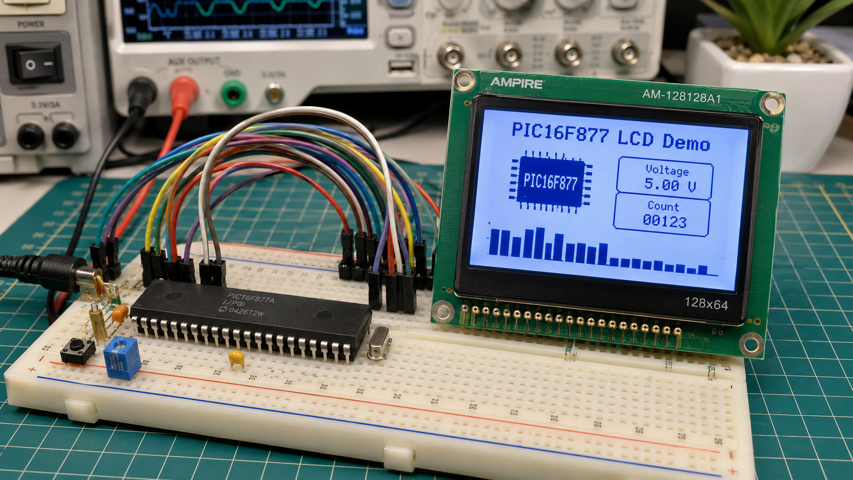
Parts used in the PIC16F877 Driving LCD Project:

  • PIC16F877 microcontroller
  • Ampire 128x64 LCD module
  • VCC power connection
  • GND connection
  • Proteus VSM simulation environment
  • Crownhill PIC BASIC Plus Compiler environment

Introduction

This project demonstrates how a PIC16F877 microcontroller can be used to drive an Ampire 128×64 LCD in a Proteus simulation environment. It is a simple but useful microcontroller project for understanding LCD interfacing in embedded systems. The design also highlights interoperability between the Crownhill PIC BASIC Plus Compiler and Proteus VSM.

For students and DIY electronics learners, this project is a practical way to explore how firmware, circuit diagram connections, and simulation tools work together. The simulation can also be paused and single-stepped, making it easier to understand the working principle of the LCD interface.

PIC16F877 LCD demo on breadboard prototype
Illustrative View of the Concept.

How the Project Works

The project uses a PIC16F877 microcontroller as the main controller and connects it to an Ampire 128×64 graphical LCD module. The firmware is written and compiled using the PIC BASIC Plus environment, then loaded into the PIC16F877 in Proteus using the generated PIC16F877 schematic part.

In the Proteus simulation, the microcontroller sends control and data signals to the LCD. These signals allow the display to initialize and show output based on the compiled firmware. The provided schematic shows multiple PIC pins connected directly to the LCD control and data pins, forming a parallel LCD interface.

This makes the project useful for learning LCD control, embedded display interfacing, and firmware testing before using real hardware.

Workflow Explanation

Workflow

 
PIC BASIC Plus Source Code

Compiled Firmware

PIC16F877 Microcontroller

Control + Data Signals

Ampire 128x64 LCD

LCD Output in Proteus Simulation

Circuit Workflow Explanation

The project begins with code written in the Crownhill PIC BASIC Plus Compiler. After compilation, the firmware is attached to the PIC16F877 inside Proteus. The PIC16F877 then communicates with the Ampire 128×64 LCD through connected control and data pins.

The LCD receives power through VCC and GND connections. The display pins such as data lines and control lines are wired to the microcontroller, allowing the PIC to control what appears on the screen during simulation.

Key Features

  • PIC16F877-based microcontroller project
  • Uses Ampire 128×64 LCD display module
  • Designed for Proteus VSM for PICMICRO
  • Demonstrates LCD interfacing using a PIC microcontroller
  • Firmware written and compiled with Crownhill PIC BASIC Plus
  • Simulation supports pausing and single-stepping
  • Can be stepped at both BASIC code level and machine code level
  • Useful for learning embedded systems and practical electronics
  • Suitable for testing firmware before hardware implementation
  • Simple circuit diagram for understanding LCD-to-PIC connections

Components Used

  • PIC16F877 microcontroller
  • Ampire 128×64 LCD module
  • VCC power connection
  • GND connection
  • Proteus VSM simulation environment
  • Crownhill PIC BASIC Plus Compiler environment

Applications

This type of embedded systems project is useful in many practical electronics and DIY electronics applications, including:

  • LCD interface learning projects
  • Embedded display control systems
  • PIC microcontroller training
  • Proteus simulation practice
  • Firmware testing before hardware development
  • Educational electronics labs
  • Basic graphical LCD demonstration projects
  • Prototype display systems for embedded devices

Explanation of Code

The source code was not provided, but the project description explains that the code is written using Crownhill PIC BASIC Plus and compiled within the PIC BASIC Plus environment.

At a high level, the firmware likely performs these main tasks based on the schematic and project description:

LCD Initialization

The microcontroller prepares the Ampire 128×64 LCD for operation by sending the required setup signals through the connected control and data pins.

LCD Data Communication

The PIC16F877 sends information to the LCD through a parallel interface. The connected pins allow the controller to transfer display data and control instructions.

Simulation Debugging

The Proteus simulation allows the firmware to be paused and single-stepped. This helps users observe how the microcontroller controls the LCD during execution.

Firmware Execution

The compiled firmware is loaded into the PIC16F877 simulation model. Once the simulation starts, the PIC executes the code and drives the LCD according to the programmed logic.

Proteus Simulation

The Proteus simulation demonstrates the PIC16F877 driving an Ampire 128×64 LCD. The circuit uses a direct connection between the PIC microcontroller and the LCD module, with VCC and GND supplied to the display.

According to the provided project note, the simulation can be paused and single-stepped either at the BASIC code level or at the machine code level. This makes the design especially useful for learning how firmware instructions control hardware behavior in a Proteus simulation.

Working Principle

The working principle is based on the PIC16F877 sending control and data signals to the LCD. The LCD receives these signals through its connected pins and displays the output generated by the firmware.

In simple terms:

  1. The PIC16F877 runs the compiled firmware.
  2. The firmware controls the LCD pins.
  3. The LCD receives command and data signals.
  4. The display responds inside the Proteus simulation.
  5. The user can pause or single-step the simulation to study the operation.

Conclusion

The PIC16F877 Driving LCD Proteus simulation is a clean and practical electronics project for learning LCD interfacing with a PIC microcontroller. It shows how firmware, a circuit diagram, and Proteus simulation work together in embedded systems development.

This project is especially helpful for beginners who want to understand graphical LCD control, PIC firmware testing, and microcontroller-based display projects before moving to real hardware.

Quick Solutions to Questions related to PIC16F877 Driving LCD Project:

  • How does the project work?
    The PIC16F877 sends control and data signals to the LCD through connected pins to initialize the display and show output based on compiled firmware.
  • What compiler is used for the firmware?
    The firmware is written and compiled using the Crownhill PIC BASIC Plus environment.
  • Can the simulation be paused?
    Yes, the Proteus simulation supports pausing and single-stepping at both the BASIC code level and machine code level.
  • What type of interface connects the microcontroller to the LCD?
    The design uses a parallel LCD interface with multiple PIC pins connected directly to the LCD control and data pins.
  • How is the firmware loaded into the simulation?
    The compiled firmware is attached to the PIC16F877 schematic part inside the Proteus simulation environment.
  • Why is this project useful for beginners?
    It allows learners to explore how firmware, circuit connections, and simulation tools work together before using real hardware.
  • What are the main tasks performed by the firmware?
    The firmware handles LCD initialization, data communication via the parallel interface, and execution of programmed logic.
  • Does the LCD receive power in the simulation?
    Yes, the LCD receives power through VCC and GND connections within the circuit diagram.

About The Author

Ibrar Ayyub

I am an experienced technical writer holding a Master's degree in computer science from BZU Multan, Pakistan University. With a background spanning various industries, particularly in home automation and engineering, I have honed my skills in crafting clear and concise content. Proficient in leveraging infographics and diagrams, I strive to simplify complex concepts for readers. My strength lies in thorough research and presenting information in a structured and logical format.

Follow Us:
LinkedinTwitter