PICC18 Calculator using PIC18F452 with Proteus Simulation

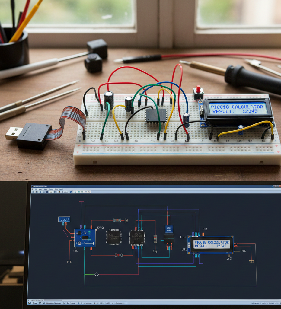
Summary of PICC18 Calculator using PIC18F452 with Proteus Simulation


This PICC18 Calculator turns a PIC18F452 into a basic four-function calculator for Proteus simulation, using a 4×4 keypad for input and a 16×2 LCD for output. It demonstrates keypad scanning, LCD interfacing, number buffering, operator chaining, floating-point operations via atof(), and division-by-zero handling with an *ERROR* message—making it a compact, extendable learning project for embedded systems.

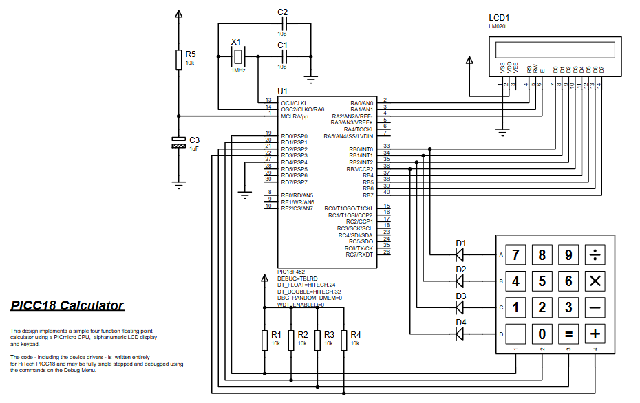
Parts used in the PICC18 Calculator:

  • PIC18F452 microcontroller
  • 16×2 LCD (LM020L) in 8-bit mode (D0–D7 plus control pins)
  • 4×4 Keypad (digits and operators)
  • Crystal oscillator X1 (1 MHz)
  • Capacitors C1, C2 (10 pF)
  • Reset capacitor C3 (1 µF)
  • Reset resistor R5 (10 kΩ)
  • Pull resistors R1–R4 (10 kΩ for keypad lines)
  • Diodes D1–D4 on keypad row lines

Introduction

This PICC18 Calculator is a compact microcontroller project that turns a PIC18F452 into a simple four-function calculator using a 4×4 keypad for input and a 16×2 LCD for output. It’s designed for Proteus simulation, so you can test the full workflow without hardware.
If you’re learning embedded systems and want a practical, hands-on build, this is a clean example of keypad scanning, LCD interfacing, and basic firmware logic. It’s also a nice “starter” project for DIY electronics where the circuit diagram and source code stay easy to follow.

Breadboard PICC18 calculator with LCD display and Proteus circuit simulation.
Illustrative View of the Concept.

How the Project Works (Overview)

The calculator continuously reads keypad presses, builds a number as a string, and shows it live on the LCD. When you press an operator (+ - * /) it stores the current number and waits for the next one. When another operator (or =) is pressed, it performs the previous operation and displays the result.

From the provided firmware:

  • Digits and . are collected into a buffer (number[])

  • Values are converted using atof()

  • The last operator is tracked (lastop)

  • The result is stored in lvalue and shown on the LCD

  • Division by zero is handled with an *ERROR* message

Block Diagram / Workflow Explanation

Input → Processing → Output flow

  1. Keypad Read

    • Firmware calls keypadread() repeatedly until a key is pressed.

  2. Key Classification

    • If key is a digit or . → add to buffer and display the typed number.

    • If key is an operator or = → evaluate the previous operation.

  3. Operation Handling

    • lvalue holds the running total.

    • rvalue holds the newly entered number.

    • lastop stores the previous operator so consecutive operations work.

  4. LCD Output

    • LCD is cleared and rewritten every time the display changes (clearscreen() + wrdata()).

Key Features (Auto-Generated)

  • Real-time number entry display on the LCD as digits are pressed

  • Four basic operations: addition, subtraction, multiplication, division

  • Floating-point support (uses FLOAT, atof(), and formatting logic)

  • Division-by-zero protection with *ERROR* display

  • Operator chaining behavior (uses lastop to process consecutive operations)

  • Proteus-friendly design using keypad + LCD routines for simulation workflows

Components Used

Identified from the provided schematic + code references:

  • PIC18F452 (PIC18 family microcontroller)

  • 16×2 LCD (LM020L) connected in 8-bit mode (D0–D7 plus control pins)

  • 4×4 Keypad (digits + operators)

  • Crystal oscillator (X1: 1 MHz) with C1, C2 = 10 pF

  • Reset / timing components: R5 = 10 kΩ, C3 = 1 µF

  • Pull resistors: R1–R4 = 10 kΩ (used on keypad lines)

  • Diodes D1–D4 on keypad row lines (as shown in schematic)

Applications

  • Learning project for keypad interfacing and LCD output

  • Practice build for embedded systems firmware structure (state + input buffer)

  • Demo project in Proteus simulation for classrooms and labs

  • Foundation for upgrades like:

    • More operators (%, √, memory keys)

    • Better formatting / precision rules

    • Clear key (C) or backspace handling

Explanation of Code (High-Level)

Main flow

  • main() initializes the LCD and then enters calculator evaluation:

    • lcd_init();

    • calc_evaluate(); (runs forever)

Input handling

  • calc_getkey() waits until keypadread() returns a non-zero ASCII key.

  • calc_testkey() returns TRUE for digits and decimal point.

Evaluation logic

  • Digits build a string buffer (number[]).

  • When an operator key appears:

    • Converts buffer to float (tmp = atof(number);)

    • Stores into lvalue or rvalue depending on whether an operator is pending

    • Executes the previous operation (calc_opfunctions(lastop))

    • Updates lastop unless key was =

Display formatting

  • calc_format() converts a float into a displayable string using divisors and inserts a decimal point at 0.1.

  • calc_display() clears the LCD and writes characters one-by-one using wrdata().

Source Code

Download
#include "calc.h"
#include "stdio.h"
#include "math.h"
#include "stdlib.h"
          
//Variables
static FLOAT lvalue = 0;
static FLOAT rvalue = 0;
static CHAR lastop;

VOID main (VOID)
// Initialise our variables and call the 
// Assembly routine to initialise the LCD display. 

Proteus Simulation

In Proteus, the 4×4 keypad acts as your input device and the LM020L LCD shows the typed digits and results. On startup, the firmware initializes the LCD and displays 0. As you press keys:

  • Digits build a number on-screen

  • Operators trigger evaluation using the previously stored operator

  • Pressing = completes the operation and resets lastop

  • Division by zero shows *ERROR*

(FAQs)

1.Why does the LCD show nothing in Proteus?

Because the display is driven through routines like lcd_init(), clearscreen(), and wrdata(). If those are missing/mismatched in your project setup, the LCD won’t update.

2.The keypad doesn’t respond—what should I check first?

The firmware waits in a loop until keypadread() returns a non-zero value. If Proteus wiring or the keypad read routine isn’t working, it will look “stuck” waiting for input.

3.Can I run this on another PIC18 device?

This project is defined for PIC18F452. Port mapping (LCD data lines, keypad lines) is schematic-specific, so moving to another PIC may require pin/port changes.

4.Why is the display formatting “custom” instead of printf?

The code uses calc_format() with divisors to control display width and decimal placement within MAX_DISPLAY_CHAR, rather than printing directly.

5.How does the project handle multiple operations in a row?

It stores the previous operator in lastop. Each time a new operator comes in, it runs calc_opfunctions(lastop) before updating lastop again.

6.What happens if I press operators without entering numbers?

The logic resets the buffer (pos = 0) and uses lastop to detect consecutive operator behavior. (Results depend on current lvalue/rvalue state.)

7.Why do I get *ERROR* sometimes?

That occurs specifically when dividing by zero (/ while rvalue == 0).

8.Can I add a Clear (C) key?

Yes—by treating a specific keypad character as a reset command (clear buffer, set lvalue/rvalue/lastop back to zero, then calc_format(0)).

Conclusion

The PICC18 Calculator is a solid, practical embedded systems project: keypad input, LCD output, and clean operator-based evaluation running on the PIC18F452 in Proteus simulation. It’s simple enough to understand quickly, but structured well enough to extend—making it a strong learning build for DIY electronics, firmware logic, and microcontroller interfacing.

Quick Solutions to Questions related to the PICC18 Calculator:

  • Why does the LCD show nothing in Proteus?
    Because the display depends on routines like lcd_init(), clearscreen(), and wrdata(); if those are missing or mismatched the LCD will not update.
  • The keypad doesn’t respond—what should I check first?
    Check that keypadread() is functioning and Proteus wiring for the keypad, since the firmware waits until keypadread() returns a non-zero value.
  • Can I run this on another PIC18 device?
    Possibly, but port mapping (LCD and keypad lines) is schematic-specific and moving to another PIC may require pin and port changes.
  • Why is the display formatting custom instead of using printf?
    The code uses calc_format() with divisors to control display width and decimal placement rather than using printf.
  • How does the project handle multiple operations in a row?
    It stores the previous operator in lastop and executes calc_opfunctions(lastop) when a new operator is entered before updating lastop.
  • What happens if I press operators without entering numbers?
    The logic resets the input buffer and uses lastop to detect consecutive operator behavior; results depend on the current lvalue and rvalue state.
  • Why do I get *ERROR* sometimes?
    *ERROR* is displayed when a division by zero occurs (division operator with rvalue equal to zero).
  • Can I add a Clear (C) key?
    Yes; treat a keypad character as a reset command to clear the buffer and set lvalue, rvalue, and lastop back to zero then call calc_format(0).

About The Author

Ibrar Ayyub

I am an experienced technical writer holding a Master's degree in computer science from BZU Multan, Pakistan University. With a background spanning various industries, particularly in home automation and engineering, I have honed my skills in crafting clear and concise content. Proficient in leveraging infographics and diagrams, I strive to simplify complex concepts for readers. My strength lies in thorough research and presenting information in a structured and logical format.

Follow Us:
LinkedinTwitter