
Summary of Power Line Communication
The project is a B.Sc. thesis (Oct 2012) implementing PLC-based serial communication over mains to connect a remote display to a weighing machine. It designs transmitter and receiver modules that filter mains frequency, modulate digital data into carrier frequencies, send the signal over the power line, then filter and demodulate at the receiver. Modulation methods discussed include FSK, FDM, and UPB pulse-based signaling.
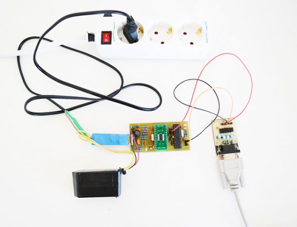
Parts used in the PLC-based serial communication project:
- Transmitter module
- Receiver module
- Mains power line (home or national grid) as transmission medium
- 50/60 Hz rejection filters (at transmitter and receiver)
- Modulator (e.g., FSK modulator)
- Demodulator (e.g., FSK demodulator)
- Frequency carrier sources (e.g., 10 kHz and 20 kHz generators for FSK)
- Multiplexer/demultiplexer for FDM
- Capacitor and pulse generation circuitry for UPB signaling
- Zero-cross detection circuitry (for UPB pulse positioning)
PLC (Power Line Communication) is the technology that allows data transmission over the existing Power Line network. Power Line can be the home power network or the national electricity transmission grid. The data that can be transferred is as diverse as its speed. With speeds of nearly 200Mbps, video transmission, voice, data and any other services can be transmitted successfully.
On this article i’m going to describe in detail my B.Sc Thesis in department of Electronic Computer Systems Engineer at Technological Education Institute of Piraeus, October of 2012 in Greece.
The project includes the design of two modules (transmitter – receiver) implementing a serial communication over the Mains connecting a remote large display to a weighing machine.
The main idea:
The main idea of the communication process is simple described in the following diagram.
From right to left, data to be transmitted are first modulated (digital bits are converted to analog frequency/sine wave e.g. bit 1 is converted to a sine wave of 10Khz bit 0 is converted to a sine wave of 20Khz). In order to “clear” the Mains frequency and make the wire available for the transmitter the 50/60Hz signal is filtered. This filter clears any signal of 50Hz to 60Hz. The transmitted data then are free to travel over the Mains. When they find their destination another 50 to 60Hz filter is involved. After the filter pass the remaining signal is the modulated transmitted data. This signal is now demodulated and converted to digital bits.
Convert data in a transferable form (Modulation):
There are different ways to modulate digital bits to a transferable frequency. I’ll describe the most commonly used types.
In FSK modulation, digital information is transmitted through discrete frequency changes of a carrier signal. For example bit 0 is modulated to a sine wave of 10Khz and bit 1 to 20Khz.
FDM is an encoding method of digital data on multiple carrier frequencies. This method allows simultaneous data transfer on the available frequency range. Firstly the information to be transmitted is separated to pieces. Each piece is modulated to a specific frequency in the available frequency range. Then all the modulated signals are multiplexed to a single signal ready for transmission.
UPB is a communication protocol specially designed for home automation devices. It uses power line wiring for signaling and control. The implementation can simple be done by charging and discharge a capacitor, forming spikes on the current AC signal.
The pulses can be placed on 4 different but specific positions on the current AC wave. It’s like a 4 bit digital number.
The receiver can simple find the position of each pulse by first recognizing the zero crossing and then start counting since the pulse sense.
For more detail: Power Line Communication
- What is the main goal of the project?
To design transmitter and receiver modules that implement serial communication over the mains to connect a remote display to a weighing machine. - How are mains frequency components handled?
50/60 Hz components are removed by filters at both transmitter and receiver so the transmitted data can use the remaining frequency range. - How is digital data converted for transmission?
Digital bits are modulated into analog carrier frequencies, for example using FSK where bit values map to different sine-wave frequencies. - What is FSK modulation in this project?
FSK transmits digital information via discrete frequency changes of a carrier, e.g., bit 0 as 10 kHz and bit 1 as 20 kHz. - How does FDM work according to the article?
Information is split into pieces, each piece is modulated onto a specific carrier frequency, and all modulated signals are multiplexed for simultaneous transmission. - What is UPB and how is it implemented?
UPB is a home automation protocol using power-line signaling implemented by charging and discharging a capacitor to create spikes at specific positions on the AC waveform. - How does the receiver detect UPB pulses?
The receiver recognizes zero crossings and then measures pulse positions relative to those crossings to interpret the pulses. - Where can this PLC communication be applied?
Over home power networks or the national electricity transmission grid to transmit services like video, voice, and data.
