Summary of PIC16F877 internal EEPROM code and Proteus simulation
This article provides C code (HI-TECH C) and a Proteus simulation to read/write the internal 256x8 EEPROM of the PIC16F877 microcontroller, showing an LED on RB0 indicating successful EEPROM programming. The code was compiled with MPLAB v8.85 and HI-TECH C v9.83; simulation used Proteus v7.10. A download link for the code and Proteus project is provided.
Parts used in the PIC16F877 EEPROM project:
- PIC16F877 microcontroller
- LED
- Current-limiting resistor for LED
- Power supply (Vcc and GND connections for PIC)
- Proteus simulation software (Proteus v7.10) for testing
- MPLAB IDE (MPLAB v8.85) for compilation
- HI-TECH C compiler (v9.83)
This post provides the internal EEPROM reading and writing code for PIC16F877 microcontroller.
As we know[1], PIC16F877 microcontroller has 256 x 8 bytes of built in EEPROM data space with an address range of 0x000 to 0x7FF. This code is written in C language using MPLAB with HI-TECH C compiler. You can download this code from the ‘Downloads‘ section at the bottom of this page.
It is assumed that you know how to blink an LED with PIC16F877 microcontroller. If you don’t then please read this page first, before proceeding with this article.
The result of simulating the code in Proteus is shown below.
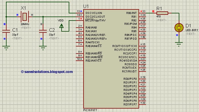
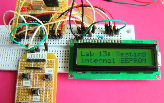
In the above circuit[2], LED attached on RB0 indicates weather a byte was successfully written in the internal EEPROM or not. In the above figure, LED is ON which indicates that EEPROM was successfully programmed.
Code
The code for the main function is shown below.
Downloads
EEPROM code for PIC16F877 was compiled in MPLAB v8.85 with HI-TECH C v9.83 compiler and simulation was made in Proteus v7.10. To download code and Proteus simulation click here.
For more detail: PIC16F877 internal EEPROM code and Proteus simulation
- What is the EEPROM size of PIC16F877?
The PIC16F877 has 256 x 8 bytes of built-in EEPROM data space with address range 0x000 to 0x7FF. - Which compiler and IDE were used for this code?
The code was compiled with HI-TECH C v9.83 using MPLAB v8.85. - How is successful EEPROM write indicated in the project?
An LED attached to RB0 is turned on to indicate that a byte was successfully written to the internal EEPROM. - In which software was the project simulated?
The project was simulated in Proteus v7.10. - Is the EEPROM read/write code provided in C?
Yes, the EEPROM read and write code for PIC16F877 is provided in C language. - Where can I download the code and simulation files?
The article provides a download link in the Downloads section for the code and Proteus simulation. - Do I need prior PIC basics before using this article?
Yes, the article assumes you know how to blink an LED with PIC16F877 and recommends reading a referenced page if you do not.