Summary of How to interface 16×2 LCD in 4-bit mode with PIC Microcontroller (PIC18F4550)
Summary: This article explains interfacing a 16x2 character LCD with a PIC18F4550 in 4-bit mode, saving microcontroller pins by using only D4–D7 for data and the usual RS, RW, EN control lines. It covers Function Set instructions (0x20 and 0x28), initialization sequence, nibble transmission (high nibble first), code to send commands/data, and circuit connections using Port B. A complete C-like source, component list, and a project video are provided.
Parts used in theProject Name:
- 16x2 character LCD module
- PIC18F4550 microcontroller
- Microcontroller power supply
- Connecting wires
- Breadboard or PCB for mounting
- Resistors (for contrast/backlight as needed)
- Potentiometer (for LCD contrast adjustment)
- Optional: USB programmer / ICSP for PIC18F4550
The 16×2 character LCD can work in two modes, namely, 8-bit and 4-bit. These modes basically correspond to the number of data pins used in interfacing LCD. 8-bit mode uses all the data lines and has been explained in LCD interfacing with PIC18F4550. In 4-bit mode, only four data pins of LCD are connected to the controller. This mode, thus, saves four pins of the controller unlike 8-bit mode. The configuration and display method of LCD in 4-bit mode has been explained here.
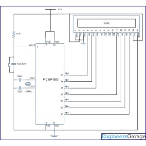
The 8-bit mode of LCD interfacing with PIC has been explained earlier. In the 4-bit mode the (8-bit) data/command is sent in nibble (four bits) format to LCD. The higher nibble is sent first followed by the lower nibble. In 4-bit mode only four data pins (D4-D7) of LCD are connected to the controller. The control pins (RS, RW and EN) are connected the same way as in 8-bit mode. The connections of LCD with PIC18F4550 are shown in the adjoining circuit diagram. Please note that here only PortB is used to connect data lines as well as control lines unlike in 8-bit mode. Refer LCD interfacing with PIC in 8-bit mode.
|
Instruction
|
RS
|
RW
|
D7
|
D6
|
D5
|
D4
|
D3
|
D2
|
D1
|
D0
|
|
Function Set
|
0
|
0
|
0
|
0
|
1
|
DL
|
N
|
F
|
–
|
–
|
|
Value
|
DL
|
N
|
F
|
|
1
|
8 bit
|
2 lines
|
5×10 dots
|
|
0
|
4 bit
|
1 line
|
5×7 dots
|
Project Source Code
###
// Program to interface 16×2 LCD with PIC18F4550 Microcontroller using 4-bit mode
// Configuration bits
/* _CPUDIV_OSC1_PLL2_1L, // Divide clock by 2
_FOSC_HS_1H, // Select High Speed (HS) oscillator
_WDT_OFF_2H, // Watchdog Timer off
MCLRE_ON_3H // Master Clear on
*/
//LCD Control pins
#define rs LATA.F0
#define rw LATA.F1
#define en LATA.F2
//LCD Data pins
#define lcdport LATB
void lcd_ini();
void dis_cmd(unsigned char);
void dis_data(unsigned char);
void lcdcmd(unsigned char);
void lcddata(unsigned char);
void main(void)
{
unsigned char data0[]=”EngineersGarage”;
unsigned int i=0;
TRISB=0; // Configure Port B as output port
LATB=0;
lcd_ini(); // LCD initialization
while(data0[i]!=”)
{
dis_data(data0[i]);
Delay_ms(200);
i++;
}
}
void lcd_ini()
{
dis_cmd(0x02); // To initialize LCD in 4-bit mode.
dis_cmd(0x28); // To initialize LCD in 2 lines, 5×7 dots and 4bit mode.
dis_cmd(0x0C);
dis_cmd(0x06);
dis_cmd(0x80);
}
void dis_cmd(unsigned char cmd_value)
{
unsigned char cmd_value1;
cmd_value1 = (cmd_value & 0xF0); // Mask lower nibble because RB4-RB7 pins are being used
lcdcmd(cmd_value1); // Send to LCD
cmd_value1 = ((cmd_value<<4) & 0xF0); // Shift 4-bit and mask
lcdcmd(cmd_value1); // Send to LCD
}
void dis_data(unsigned char data_value)
{
unsigned char data_value1;
data_value1=(data_value&0xF0);
lcddata(data_value1);
data_value1=((data_value<<4)&0xF0);
lcddata(data_value1);
}
void lcdcmd(unsigned char cmdout)
{
lcdport=cmdout; //Send command to lcdport=PORTB
rs=0;
rw=0;
en=1;
Delay_ms(10);
en=0;
}
void lcddata(unsigned char dataout)
{
lcdport=dataout; //Send data to lcdport=PORTB
rs=1;
rw=0;
en=1;
Delay_ms(10);
en=0;
}
###
Circuit Diagrams
Project Components
Project Video
Source: How to interface 16×2 LCD in 4-bit mode with PIC Microcontroller (PIC18F4550)
- What is the advantage of using 4-bit mode over 8-bit mode?
4-bit mode saves four controller data pins by using only D4–D7 for data instead of all eight data lines. - Which LCD data pins are used in 4-bit mode?
Only data pins D4 through D7 of the LCD are connected to the controller in 4-bit mode. - How is an 8-bit byte sent to the LCD in 4-bit mode?
The 8-bit data/command is sent as two nibbles: the higher nibble first, followed by the lower nibble. - What control pins are required for the LCD connection?
The control pins RS, RW and EN are used the same way as in 8-bit mode. - What is the Function Set value to switch LCD to 4-bit mode?
To select 4-bit mode the Function Set value 0x20 (binary 0010 0000) is used; for 2 lines and 5x7 dots in 4-bit mode the value is 0x28 (0010 1000). - Why is 0x02 sent instead of 0x20 at power-up?
At power-up the LCD defaults to 8-bit mode, so because only D4–D7 are connected the 0x02 nibble is sent to properly start 4-bit initialization. - What port is used for data and control lines in the provided circuit?
Port B of PIC18F4550 is used to connect both data lines and control lines in the shown circuit. - Which initialization commands are used in the example code?
The code sends 0x02, 0x28, 0x0C, 0x06, and 0x80 during LCD initialization.