Summary of 4-digit Up/Down counter with preset, reset, hold and overflow output using PIC16F88
This article describes a 4-digit decimal counter built using a PIC16F88 microcontroller. It features up/down counting, manual reset, preset values, and overflow/underflow outputs. The device supports free-running or count-and-hold modes with configurable clock edges and leading zero suppression. Display components include multiplexed 7-segment LEDs and indicator LEDs, driven by a Schmitt trigger input capable of handling frequencies up to 5kHz.
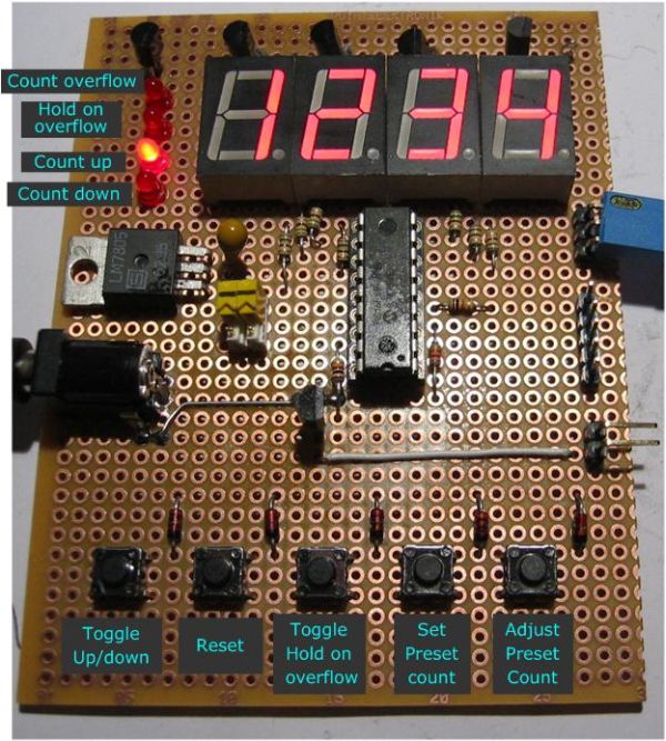
Parts used in the 4-Digit Up/Down Counter:
- PIC 16F88 microcontroller
- Four single digit 7-segment LEDs (common anode)
- Indicator LEDs
- Schmitt trigger input pin
- Set switch
- Adjust keys
- Debounce circuit
Overview
A four digit decimal counter for the PIC 16F88 with the following features:
- Count up / down
- Reset
- Free running or hold on count over/underflow
- User count preset
- Over/underflow output
This is a 4 digit decimal counter which can operate as a free running counter or in count and hold mode with manual reset. In either mode the counter can be preset to count to a specified value. Clock edge and leading zero suppression can also be configured.
The 7-segment display and indicator LEDs are multiplexed. It will drive most common anode 7 segment LEDs. I used four single digit LEDs but a four digit LED module could also be used.
In free running mode the overflow output resets on the next clock pulse. Therefore the pulse duration is directly related to the input clock frequency.
The clock input goes to a Schmitt trigger input pin on the PIC. It will accept a 0-5V input signal only. If it’s used with a mechanical switch you should use the debounce circuit shown on the schematic.
I’ve had the circuit clock reliably at 200Hz and it should be able to operate without missing a clock pulse at frequencies up to 5Khz.
Operation
The counter can be configured for either a rising or falling clock edge and leading zero suppression. Once applied these settings are stored in NVRAM and retained across a power cycle. To enter config mode, hold down the ‘set’ switch at power-on.
The counter normally runs from 0000 to 9999.
It can be configured to count up to, or down from a preset number using the set and adjust keys.
The preset number is used until it is manually changed. When it has been changed the preset is saved to EEPROM and will be restored at power on.
Overflow:-
Active when count reaches preset value
Count Hold:-
On – Counter in Hold mode
Off – Counter in free running mode
Count Up / Count Down :-
indicates the count direction
For more detail: 4-digit Up/Down counter with preset, reset, hold and overflow output using PIC16F88
- What is the maximum operating frequency for this counter?
The circuit should be able to operate without missing a clock pulse at frequencies up to 5Khz. - How do I enter configuration mode?
To enter config mode, hold down the set switch at power-on. - Can the counter count both up and down?
Yes, the counter can be configured to count up to or down from a preset number. - Does the preset value persist after a power cycle?
Yes, when changed, the preset is saved to EEPROM and will be restored at power on. - What type of 7-segment display does it drive?
It drives most common anode 7 segment LEDs. - Is a debounce circuit required for mechanical switches?
Yes, if used with a mechanical switch you should use the debounce circuit shown on the schematic. - What happens in free running mode when the overflow output activates?
The overflow output resets on the next clock pulse. - Can leading zero suppression be configured?
Yes, clock edge and leading zero suppression can also be configured.