Summary of How to use input output ports 8051 microcontroller|LED blinking
This article explains the PIC16F877A microcontroller's five parallel I/O ports (PORTA to PORTE) and their configuration via TRIS registers, where 0 sets an output and 1 sets an input. It details connecting LEDs to PORTD for alternating blinking using a C-like code example involving left and right shifts with delays. The text also introduces PIC Simulator IDE as a graphical development tool supporting Microchip MCUs and provides specific configuration words and frequency settings for the project.
Parts used in the PIC16F877A LED Blinking Project:
- PIC16F877A chip
- Eight Light Emitting Diodes (LEDs)
- PIC Simulator IDE software
- Microchip 8-bit PIC Mid-Range architecture MCU
- TRIS register
- PORTD pins
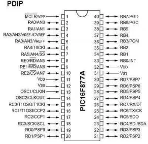
PIC16F877A Pin out & Descriptions
There are 5 ports that provide parallel I/O Interfaces to outside world PORTA, PORTB, PORTC, PORTD, PORTE
Each port provides 8 bidirectional digital I/O lines which are connected to PIC16F877A pins provided that alternate functions are not selected on that Port.
Eventhough Bidirectional at nay time the I/O line can either be INPUT or OUTPUT.
By clearing some bit of the TRIS register (bit=0), the corresponding port pin is configured as output. Similarly, by setting some bit of the TRIS register (bit=1), the corresponding port pin is configured as input. This rule is easy to remember 0 = Output, 1 = Input.
Step 1: Connection of LEDs With a Port
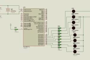
Let us assume that 8 LEDs are connected to 8-pins of PORTD of an PIC16F877A chip.
We want to glow eight LEDs alternately. [If ‘1’ is sent, the corresponding LED glows]
And they will toggle at every 1 sec and it will be repeated continuously.
Write a C code or Basic code for the above mentioned output operations
Light Emitting Diode (LED) is a special diode that emits light when electric voltage is applied to it. It is a common electronic equipment used in many devices for indication purpose.
Step 2: Summary Action During Output
Step1: If we want to read (in) data through a pin of a port, the corresponding bit of TRISx Register has to be set to ‘0’.
Step 2: Whatever data is in that pin of the port the data will appear in the corresponding bit of TRISx register.
Step 3: Each pin has a provision of connecting a pull up resistor internally. If we want to connect that resistor, we have to write ‘1’ to the corresponding bit of PORTx register.
Note: At START UP or UPON RESET, TRISx register contains 0x00. That is the port remains at Input state. But if it is used as OUTPUT at one stage of program, afterwards, we can not read data from a pin if we do not complete step 1.
Step 3: PIC SIMULATOR IDE
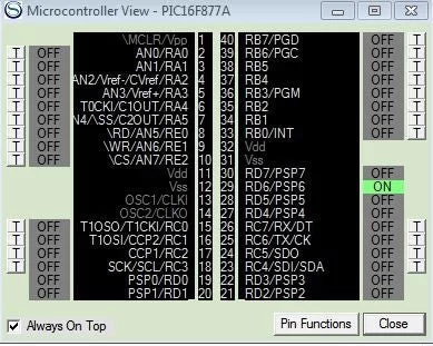
PIC Simulator IDE is powerful application that supplies Microchip microcontroller users with user-friendly graphical development environment for Windows with integrated simulator (emulator), pic basic compiler, assembler, disassembler and debugger. PIC Simulator IDE supports the extensive number of microcontrollers (MCUs) from the Microchip 8-bit PIC Mid-Range architecture product line (selected PIC16F, PIC12F, PIC10F models).
Step 5: Code
Define CONF_WORD = 0x3f72
Define CLOCK_FREQUENCY = 12 ‘clock frequency
AllDigital ‘all ports goes to digital
TRISD = 0x00 ‘PORTD output
PORTD = %00000001 ‘RD0 is on and other pin off or zero
goleft: ‘for left shift loop
WaitUs 500 ‘delay 500us
PORTD = ShiftLeft(PORTD, 1) ‘portd shiftleft from rd0
If PORTD.7 Then Goto goright ‘when RD7=1 then goto loop right shift
Goto goleft ‘repet loop
goright: ‘right shift loop
WaitUs 500 PORTD = ShiftRight(PORTD, 1) ‘shift right
If PORTD.0 Then Goto goleft ‘when RD0=1 then goto left shift loop
Goto goright
Source: How to use input output ports 8051 microcontroller|LED blinking
- How many ports provide parallel I/O interfaces on the PIC16F877A?
There are 5 ports that provide parallel I/O Interfaces to the outside world. - What value configures a port pin as an output?
Clearing a bit of the TRIS register by setting it to 0 configures the corresponding port pin as an output. - What happens when a '1' is sent to a connected LED pin?
If '1' is sent, the corresponding LED glows. - What is the default state of the TRISx register at startup or reset?
At startup or upon reset, the TRISx register contains 0x00, meaning the port remains in the Input state. - How do you enable the internal pull-up resistor for a pin?
You must write '1' to the corresponding bit of the PORTx register to connect the internal pull-up resistor. - Which software is described as a powerful application for graphical development?
PIC Simulator IDE is the powerful application supplying a user-friendly graphical development environment. - What clock frequency is defined in the provided code example?
The code defines the clock frequency as 12. - What condition triggers the transition from the left shift loop to the right shift loop?
The program goes to the right shift loop when RD7 equals 1.