GSM modules are fascinating to use especially when our project requires remote access. These modules could make all actions that our normal mobile phone could do, like making/receiving a call, sending/receiving a SMS, connecting to internet using GPRS etc. You can also connect a normal microphone and speaker to this module and converse on your mobile calls. This will open doors to lot of creative projects if it could be interfaced with a Microcontroller. Hence in this tutorial we will learn how we can Interface the GSM module (SIM900A) with our PIC microcontroller and will demonstrate it by making and receiving call using GSM Module. We have previously interfaced it with Arduino and Raspberry Pi for calling and messaging:
Materials Required:
- PIC Microcontroller (PIC16F877A)
- GSM module (SIM900 or any other)
- Connecting wires
- 12V Adapter
- PicKit 3
GSM Module:
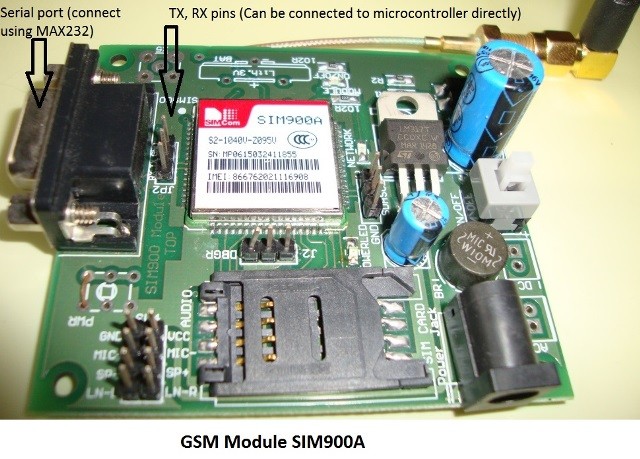
The GSM module can be used even without any microcontroller by using the AT command mode. As shown above the GSM module comes with a USART adapter which can be directly interfaced to the computer by using a MAX232 module or the Tx and Rx pins can be used to connect it to a Microcontroller. You can also notice the other pins like MIC+, MIC-, SP+, SP- etc where a microphone or a Speaker can be connected. The module can be powered by a 12V adapter through a normal DC barrel jack.
Insert your SIM card in the slot of the module and power it on, you should notice a power LED going ON. Now wait for a minute or so, and you should see a red (or any other colour) LED Flashing once for every 3 seconds. This means that your Module was capable to establish connection with your SIM card. Now you can proceed with connecting you module with Phone or any Microcontroller.
Communicating with GSM module using AT commands:
As you might have guessed it, the GSM module can communicate through Serial communication and could understand only one language and that is “AT commands”. Whatever that you might want to tell or ask to the GSM module it should only be via AT commands. For example if you want to know if your module is active. You should ask (send) a command like “AT” and your module will reply “OK”.
These AT commands are well explained in its data sheet and can be found here in its official datasheet. Okay! Okay! It is a 271 page datasheet and you might take days to read through them. So I have given some most important AT commands below for you to get this up and running soon.
AT | Replies with OK for Acknowledgement | ||||
AT+CPIN? | Check signal Quality | ||||
AT+COPS? | Find service provider name | ||||
ATD96XXXXXXXX; | Call to the specific number, ends with semi-colon | ||||
AT+CNUM | Find the number of SIM card (might not work for some SIM) | ||||
ATA | Answer the Incoming Call | ||||
ATH | Hang off the current Incoming call | ||||
AT+COLP | Show incoming call number | ||||
AT+VTS=(number) | Send DTMF number. You can use any number on your mobile keypad for (number) | ||||
AT+CMGR | AT+CMGR=1 reads message at first position | ||||
AT+CMGD=1 | Delete message at first position | ||||
AT+CMGDA=”DEL ALL” | Delete All messages from SIM | ||||
AT+CMGL=”ALL” | Read all messaged from SIM | ||||
AT+CMGF=1 | Set SMS configuration. “1” is for text only mode | ||||
AT+CMGS = “+91 968837XXXX” >CircuitDigest Text<Ctrl+z> | Sends SMS to a particular number here 968837XXXX. When you see “>” start entering the text. Press Ctrl+Z to send the text. | ||||
AT+CGATT? | To check for internet connection on SIM card | ||||
AT+CIPSHUT | To close TCP connection, meaning to disconnect form internet | ||||
AT+CSTT = “APN”,”username”,”Pass” | Connect to GPRS with your APN and Pass key. Can be obtained from Network Provider. | ||||
AT+CIICR | Check if SIM card has data pack | ||||
AT+CIFSR | Get IP of the SIM network | ||||
AT+CIPSTART = “TCP”,”SERVER IP”,”PORT” | Used to set a TCP IP connection | ||||
AT+CIPSEND | This command is used to send data to server |
Circuit Diagram:
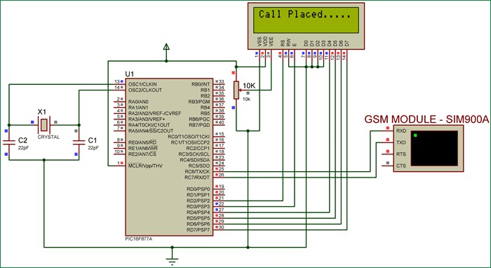
The connection diagram for Interfacing GSM module with PIC microcontroller is shown below.
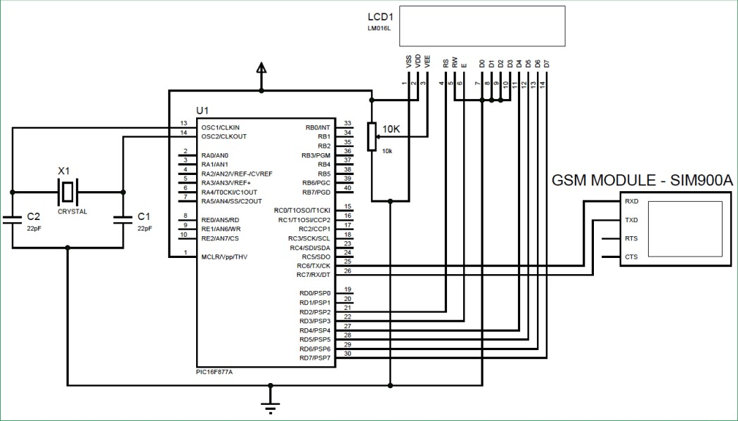
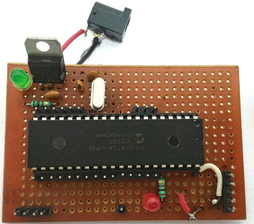
We have simply interfaced the Tx and Rx pins of the GSM module with the Rx and Tx pins of the PIC MCU PIC16F877A respectively. This will establish a Serial connection between both. Also, so do not forget to common ground both the GSM and PIC module. We have also used a LCD display to know the status of our GSM module. Once the connections are done your hardware will look like something below.
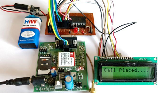
The PIC Perf board was made for our PIC tutorial series, in which we learnt how to use PIC microcontroller. You might want to go back to those PIC Microcontroller tutorials using MPLABX and XC8 if you do not know how to burn a program using Pickit 3, since I will be skipping all those basic information.
Programming you PIC Microcontroller:
The complete program for this project can be found at the bottom of this tutorial. Here I will explain some important functions and pieces of code. This program also has a LCD codes which were from Interfacing LCD with PIC Microcontroller, you can visit that tutorial if you are curious to know how LCD can be used with PIC microcontroller.
As said earlier, we are going to communicate between PIC and GSM using AT commands through the Serial mode of communication. So, first we have to initialize the USART communication module in our PIC microcontroller by using the Initialize_SIM900(); function. Inside this function we declare the Tx and RX pins and initialize Asynchronous reception and transmission at 9600 baud rate and 8-bit mode.
//***Initialize UART for SIM900**//
void Initialize_SIM900(void)

{
    //****Setting I/O pins for UART****//
    TRISC6 = 0; // TX Pin set as output
    TRISC7 = 1; // RX Pin set as input
    //________I/O pins set __________//


    /**Initialize SPBRG register for required
    baud rate and set BRGH for fast baud_rate**/
    SPBRG = 129; //SIM900 operates at 9600 Baud rate so 129
    BRGH  = 1;  // for high baud_rate
    //_________End of baud_rate setting_________//

    //****Enable Asynchronous serial port*******//
    SYNC  = 0;    // Asynchronous
    SPEN  = 1;    // Enable serial port pins

    //_____Asynchronous serial port enabled_______//
    //**Lets prepare for transmission & reception**//
    TXEN  = 1;    // enable transmission
    CREN  = 1;    // enable reception
    //__UART module up and ready for transmission and reception__//

    //**Select 8-bit mode**//
    TX9   = 0;    // 8-bit reception selected
    RX9   = 0;    // 8-bit reception mode selected
    //__8-bit mode selected__//
}
//________UART module Initialized__________//
Now we need to read and write information from/to our GSM module. For this we use the functions _SIM900_putch(), _SIM900_getch(), _SIM900_send_string(), _SIM900_print(). These functions use the Transmit and receive buffer register such as TXREG and RCREG to read or write data serially.
//**Function to send one byte of date to UART**//

void _SIM900_putch(char bt)
{
    while(!TXIF);  // hold the program till TX buffer is free
    TXREG = bt; //Load the transmitter buffer with the received value
}

//_____________End of function________________//


//**Function to get one byte of date from UART**//
char _SIM900_getch()
{
    if(OERR) // check for Error
    {
        CREN = 0; //If error -> Reset
        CREN = 1; //If error -> Reset
    }
   while(!RCIF);  // hold the program till RX buffer is free
    return RCREG; //receive the value and send it to main function
}
//_____________End of function________________//

//**Function to convert string to byte**//
void SIM900_send_string(char* st_pt)
{
    while(*st_pt) //if there is a char
        _SIM900_putch(*st_pt++); //process it as a byte data
}
//___________End of function______________//
//**End of modified Codes**//

void _SIM900_print(unsigned const char *ptr) {
    while (*ptr != 0) {
        _SIM900_putch(*ptr++);
    }
The above functions are universal and need not be changed for any applications. They were explained only to give a rough intro. You can dive deep into them if you want through understanding.
Now inside our main function, we initialize the USART connection and check if we are able to receive a “OK” when we send “AT” by using the below line of code
do
    {
    Lcd_Set_Cursor(2,1);
    Lcd_Print_String("Module not found");
    }while (!SIM900_isStarted()); //wait till the GSM to send back "OK"
    Lcd_Set_Cursor(2,1);
    Lcd_Print_String("Module Detected ");
    __delay_ms(1500);
The function SIM900_isStarted(); will send “AT” to the GSM and waits for response “OK” from it. If yes, it will return 1 else 0;
If the module is not detected or if there is any connection problem then the LCD will show “Module not found”, else it will show Module is detected and proceed to next step where, we check if the SIM card can be detected by the below line of code.
/*Check if the SIM card is detected*/
    do
    {
    Lcd_Set_Cursor(2,1);
    Lcd_Print_String("SIM not found   ");
    }while (!SIM900_isReady()); //wait till the GSM to send back "+CPIN: READY"
    Lcd_Set_Cursor(2,1);
    Lcd_Print_String("SIM Detected    ");
    __delay_ms(1500);
The function SIM900_isReady() will send “AT+CPIN?” to the GSM and waits for response “+CPIN: READY” from it. If yes, it will return 1 else 0;
If a SIM card if found we will get SIM detected displayed on the LCD. Then, we can try placing a call by using the command “ATDmobilenumber;”. Here as an example I have used my number as ATD93643159XX;. You have to replace your respective mobile number there.
   /*Place a Phone Call*/
     do
    {
    _SIM900_print("ATD93643XXXXX;\r\n");  //Here we are placing a call to number 93643XXXXX
    Lcd_Set_Cursor(1,1);
    Lcd_Print_String("Placing Call....");
    }while (_SIM900_waitResponse() != SIM900_OK); //wait till the ESP send back "OK"
    Lcd_Set_Cursor(1,1);
    Lcd_Print_String("Call Placed....");
    __delay_ms(1500);
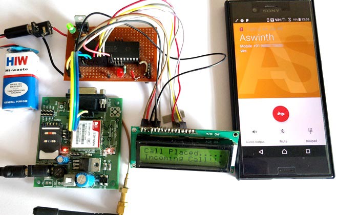
Once the call is placed the LCD will display Call Placed and you should receive an incoming call to that specified number.
You can also call to the mobile number connected to the GSM module and get notified about it on your LCD screen y using the below code
    while(1)
    {
        if (_SIM900_waitResponse() == SIM900_RING) //Check if there is an incoming call
        {
          Lcd_Set_Cursor(2,1);
          Lcd_Print_String("Incoming Call!!.");
        }
    }
When the GSM module detects a incoming call it will display Incoming call on the second line of the LCD module. The function _SIM900_waitResponse() will check for incoming data from the GSM module. When it receives SIM900_RING, which is equivalent to “RING” due to the waitResponce(), we will display the status “Incoming call”.
You can create your own functions like this to perform almost all types of activates using GSM module. If you want to have things hardcoded, you can simply use the __SIM900_print() function to send any AT command like this below.
_SIM900_print("AT+CPIN?\r\n");Remember that all you command should be followed with “\r\n” to indicate that the command is terminating.
Simulation:
Once you have understood how the program works you can try simulating and make changes to fit your needs. Simulation will save you a lot of time. The simulation is done using Proteus and it looks like below.
As you can see we have used virtual terminal option in Proteus to check if the Program is responding as expected. We can feed in the values through the pop-up dialog box. For example as soon as we hit run, a black dialog box like above will appear and display AT, this means that it has send the GSM module AT, now we can reply to PIC by typing in the box as “OK” and hit enter and the PIC will respond to it. Similarly we can try for all AT commands.
Making and Receiving calls using GSM and PIC:
Once you understand how the code and hardware works, simply upload the below program to PIC and power on the module. Your LCD should display “Module Detected”, “SIM detected” and “call Placed” if everything is working fine. Once you see “Call placed” you will get a incoming call to the number specified in the program.
You can also try calling to the number present in the GSM module and your LCD will display “Incoming call” to indicate the SIM is being called.

Whole Project Working Video: