Summary of PIC12F1822 + DS3231 + Remote Control
This project demonstrates building a Real Time Clock (RTC) using a PIC12F1822 microcontroller, DS3231 module, and 1602 LCD. Due to pin limitations, an IR receiver connected to a Car MP3 remote replaces physical set buttons. The system uses I2C for the RTC and a shift register to drive the LCD display, with time editing controlled via specific remote button codes.
Parts used in the PIC12F1822 Real Time Clock:
- PIC12F1822 microcontroller
- DS3231 board
- 1602 LCD screen
- 74HC595 shift register
- IR receiver
- 10K ohm variable resistor
- 47uF capacitor
- 5V supply source
- Breadboard
- Jumper wires
PIC12F1822 is a small microcontroller has only 8 pins which is not enough for building a real time clock using DS3231 with set buttons because the DS3231 needs 2 pins and the LCD screen needs 3 pins, therefore I’ve only 1 free pin. I connected that pin to an IR receiver and I used a remote control with a lot of buttons where I used only 3 buttons and the problem solved.
This post shows how did I build a simple real time clock using PIC12F1822, 1602 LCD and DS3231 with Car MP3 IR remote control (NEC protocol RC).
Before this project I made a NEC remote control decoder using PIC12F1822 MCU:
Extended NEC Protocol Decoder Using PIC12F1822 Microcontroller
Time and calendar are displayed on 1602 LCD with the help of a serial-in parallel-out shift register (74HC595, 74HC164, CD4094 …..) as what I made in the example below:
Interfacing PIC12F1822 microcontroller with LCD display
The DS3231 uses I2C protocol to interface with the master device which is in our example the PIC12F1822 MCU which has one I2C module.
The I2C protocol uses only two lines: SCL (Serial Clock) and SDA (Serial Data) which are in the PIC12F1822 pin RA1 and pin RA2 respectively.
Hardware Required:
- PIC12F1822 microcontroller
- DS3231 board – datasheet
- 1602 LCD screen
- 74HC595 shift register (74HC164 and CD4094 can be used)
- IR receiver
- 10K ohm variable resistor
- 47uF capacitor
- 5V supply source
- Breadboard
- Jumper wires
The Circuit:
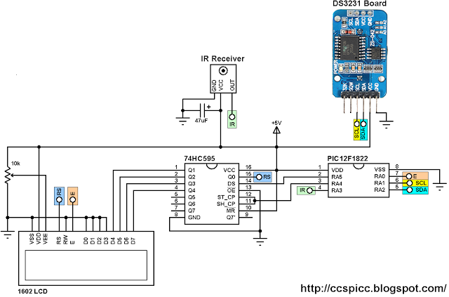
The IR receiver has 3 pins: GND, VCC and OUT. Pin OUT is connected to pin RA3 of the PIC12F1822.
The LCD screen with the 74HC595 shift register are connected to pins: RA0 (Enable), RA4 (Data) and RA5 (Clock).
The DS3231 board SCL and SDA are connected to pins RA1 and RA2 respectively.
In this project the PIC12F1822 uses its internal oscillator and MCLR pin is configured as a digital pin.
The Code:
The C code below was tested with CCS C compiler version 5.051.
The hardware I2C module of the PIC12F1822 MCU is initialized and configured using the function below with a speed of 100KHz:
#use I2C(master, I2C1, FAST = 100000)
I2C1: use first I2C module.
The DS3231 works with BCD format only and to convert the BCD to decimal and vise versa I used the 2 functions below. Before displaying (after reading from DS3231), the data have to be converted from BCD to decimal, and before writing to the DS3231 (after editing the parameters) the data have to be converted from decimal to BCD:
int8 bcd_to_decimal(number)
int8 decimal_to_bcd(number)
Each function returns the converted value of the variable number.
void DS3231_display() : displays time and calendar data, before displaying time and calendar data are converted from BCD format to decimal format using the function bcd_to_decimal(number) .
int8 edit(x, y, parameter) : I used this function to edit time calendar parameters (minutes, hours, date, month and year). I used a variable named i to distinguish between the parameters:
i = 0, 1 : time hours and minutes respectively
i = 2, 3, 4: calendar date, month and year respectively
After the edit of time and calendar, the data have to be converted back to BCD format using the function decimal_to_bcd(number) and written back to the DS3231.
void blink() : this small function works as a delay except that it is interrupted by the IR remote control codes for buttons 1, 2 and 3. When called and without pressing any of the three button the total time is 10 x 25ms = 250ms. With this function we can see the blinking of the selected parameter with a frequency of 2Hz. So a delay of 250ms comes after the print of the selected parameter and after that delay a 2 spaces is printed which makes the parameter disappears from the LCD and another 250ms delay comes after the print of the 2 spaces.
The remote control buttons and their codes are shown in the image below: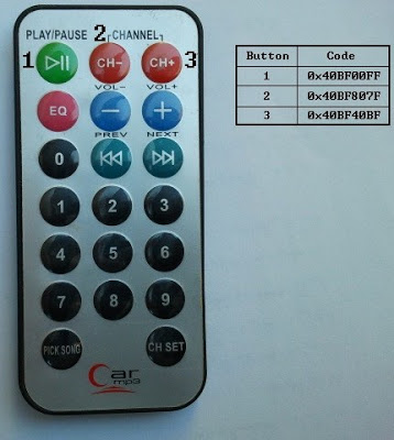
for more detail: PIC12F1822 + DS3231 + Remote Control
- How was the pin shortage solved?
An IR receiver connected to a Car MP3 remote control was used to replace physical set buttons. - Which pins does the DS3231 use for I2C communication?
The DS3231 connects to RA1 for SCL and RA2 for SDA on the PIC12F1822. - What is the function of the 74HC595 shift register?
It interfaces the serial data from the microcontroller to the parallel input required by the 1602 LCD screen. - Does the DS3231 support decimal format directly?
No, the DS3231 works with BCD format only and requires conversion functions for decimal display or input. - What compiler version was used for the C code?
The code was tested with CCS C compiler version 5.051. - How does the blink function work during editing?
It creates a 2Hz blinking effect by interrupting a delay loop with IR remote button codes. - Can other shift registers be used instead of 74HC595?
Yes, 74HC164 and CD4094 can be used as alternatives. - What protocol does the remote control use?
The project uses the NEC protocol RC found on a Car MP3 remote.