
Summary of MikroElektronika’s “Ready for PIC” board talks to “Processing” using PIC16F887
The "Ready for PIC" article details a compact prototyping board featuring the PIC16F887 microcontroller with a preprogrammed UART bootloader, enabling direct PC communication via an onboard USB-UART module without external programmers. The project demonstrates creating a Processing application to send time data to the board, which then displays it on a seven-segment LED module. This setup facilitates embedded projects requiring PC interfacing and serial data transfer.
Parts used in Ready for PIC Project:
- Ready for PIC prototyping board
- PIC16F887 microcontroller (in DIP40 socket)
- FT232RL chip (USB to UART interface)
- Processing software development environment
- Serial 7-Seg 8-Digit Board (with MAX7219 chip)
- IDC10 connector cable
- USB cable
- 2×5 male header pins
“Ready for PIC“ is one of MikroElektronika‘s compact prototyping boards for 28 and 40 pin PIC microcontrollers. The board comes with PIC16F887 microcontroller which is preprogrammed with an UART bootloader firmware and thus eliminates the need of an external programmer. The on-board USB-UART module allows the serial data transfer between the PIC and a PC using an USB cable. It has also got a reasonable size prototyping area to add more functionalities to the board as required. These features make this board an ideal candidate for doing embedded projects that require PC interfacing. This article first reviews the basic features of the Ready for PIC board and then demonstrates how to write a PC application in Processing (an open source programming language) to communicate with the board through the on-board USB-UART module.
A brief review of Ready for PIC board
Ready for PIC is a compact development tool for 28/40 pin PIC microcontrollers. The board by default is equipped with PIC16F887 MCU placed in a DIP40 socket but it does provide connection holes to accommodate a 28-pin device. To program the MCU you can either use the pre-installed bootloader or an external programmer. For using an external programmer, you need to make a few adjustments on the board. Please read the User’s Manual for further instructions on this. Four 2×5 male header pins are available on the board for easy access to the MCU I/O pins. The on-board FT232RL chip provides a USB to asynchronous serial data transfer interface so that the MCU can communicate with a PC through a virtual COM port using a USB cable. The board has two LEDs marked with Rx and Tx which blink when data transfer via USB UART module is active. The board can also be used with a 3.3 V type PIC microcontroller. There is an on-board jumper for selecting between 5 V and 3.3 V supply voltage for the MCU.
Little about Processing
Processing is an open-source software development environment designed for simplifying the process of creating digital images, animations and interactive graphical applications. It is free to download and operates on Mac, Windows, and Linux platforms. The Processing Interactive Development Environment (IDE) has the same basic structure as that of the Arduino IDE and is very easy to use. The programming language is so simple that you can create an interactive graphics with just a few lines of code. Here we will not discuss much of the graphics capability of Processing. We will rather focus on the Processing Serial library that will allow to transfer data between the PC and the Ready for PIC board.
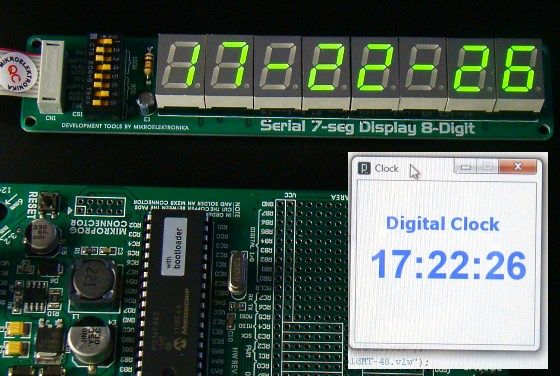
We will write a simple program in Processing to create a graphics window that displays the current computer time, and will send the same information to the Ready for PIC board through the virtual COM port. The PIC microcontroller will then display the time on a 8-digit seven segment LED display module. The seven segment LED module used here is mikroElektronika’s Serial 7-Seg 8-Digit Board. It uses a MAX7219 chip to drive 8 seven segment LEDs. The chip receives the display data from a microcontroller through an SPI serial interface. An User’s Manual is available for the Serial 7-Seg 8-Digit Board that describes how to use it with mikroElektronika’s various development boards. The LED board comes with an IDC10 connector cable that can be plugged into one of the 2×5 male header connectors on the Ready for PIC board. I connected it to PORTC of PIC16F887 (as shown below) because the SPI data and clock pins are multiplexed with PORTC I/O pins (see PIC16F887 datasheet for detail).
For more detail: MikroElektronika’s “Ready for PIC” board talks to “Processing” using PIC16F887
-
What is the main purpose of the Ready for PIC board?
It is a compact prototyping tool for 28 and 40 pin PIC microcontrollers designed for embedded projects requiring PC interfacing. -
How does the board communicate with a PC?
It uses an on-board FT232RL chip to provide a USB to asynchronous serial data transfer interface via a virtual COM port. -
Is an external programmer required to use this board?
No, the board comes with a preprogrammed UART bootloader firmware that eliminates the need for an external programmer. -
What voltage options are available for the microcontroller?
The board has an on-board jumper allowing selection between 5 V and 3.3 V supply voltage for the MCU. -
How can I access the MCU I/O pins on the board?
Four 2×5 male header pins are available on the board for easy access to the MCU I/O pins. -
Which chip drives the eight seven segment LEDs in the display project?
A MAX7219 chip is used to drive the 8 seven segment LEDs on the Serial 7-Seg 8-Digit Board. -
Where was the SPI connection connected on the PIC16F887?
The author connected the LED board to PORTC because the SPI data and clock pins are multiplexed with PORTC I/O pins. -
Can the Ready for PIC board accommodate 28-pin devices?
Yes, while it defaults with a DIP40 socket, it provides connection holes to accommodate a 28-pin device.
