
Summary of Using Serial Peripheral Interface (SPI) with Microchip PIC18 Families Microcontroller
The article introduces the Serial Peripheral Interface (SPI) as a fast, simple embedded communication protocol capable of 10 MHz transfer speeds using an 8-bit circular shift register. It highlights that while SPI masters initiate all transfers, slaves can use interrupt pins to notify the master of data readiness, avoiding resource-heavy polling. The tutorial specifically demonstrates this setup using the Microchip PIC18F14K22 microcontroller, which features built-in peripherals like ADC, USART, and SPI modules.
Parts used in the SPI with PIC18F14K22 Project:
- SPI Master Device
- SPI Slave Device
- Microchip PIC18F14K22 Microcontroller
- ADC Module
- USART Module
- ECCP Module
- I2C Module
- SR Latch Module
The Serial Peripheral Interface (SPI) is one of the popular embedded serial communications widely supported by many of today’s chip manufacture and it considered as one of the fastest serial data transfer interface for the embedded system. Because of its special in/out register configuration, the SPI master device could transfer its data and at the same time it receive a data from the SPI slave device with the clock speed as high as 10 MHz. Beside its superior data transfer speed; SPI also use a very simple data transfer protocol compared to the other serial data transfer methods. When the SPI master device want to send the data to the SPI slave device then the SPI master will just simply shifting its own data through a special 8-bits register and at the same time the SPI master will receive the data from the SPI slave into the same register as shown on this following picture: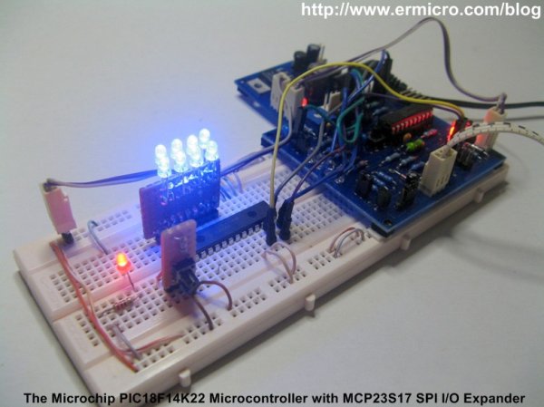
With this circular shift register connection between the SPI master and the SPI slave devices, the complete data transfer from both devices will be accomplished in just 8 clock cycles. This means the SPI devices only need about 0.8 us to complete transfer the 8-bit data if we use 10 MHz clock. One of the drawbacks using the SPI especially when we use multiple SPI slave device is the SPI slave could not initiate sending its own data to the SPI master device, all the data transfer initiation is always come from the SPI master. The SPI master device has to poll each of the SPI slave devices to know whether the SPI slave device has a data to be sent to the SPI master device or not.
Polling the entire SPI slave devices will eventually consumed the SPI master resources when the SPI slave devices to be polled increase, therefore some of the SPI slave device is equipped with the interrupt pin to notify the SPI master device that it has a data to be read. You could read more about how SPI work in my previous posted blog Using Serial Peripheral Interface (SPI) Master and Slave with Atmel AVR Microcontroller.
The PIC18F14K22 Microcontroller
On this tutorial I will use the Microchip PIC18F14K22 microcontroller, this microcontroller is one of my favorite 8-bit 20-pins PIC18 microcontroller families members as it is equipped with sophisticated advanced peripheral inside such as ADC, USART, ECCP (Enhanced Capture/Compare/PWM), SPI, I2C and the SR Latch (555 Timer) module for capacitive sensing. With 16K bytes flash ram and equipped with the build in circuit debug, this 8-bit 20-pins microcontroller is a perfect choice for serious embedded application or just for hobbyist’s project.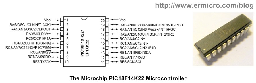
For more detail: Using Serial Peripheral Interface (SPI) with Microchip PIC18 Families Microcontroller
- What is the maximum clock speed for SPI data transfer mentioned?
The SPI master device can receive and transfer data at a clock speed as high as 10 MHz. - How many clock cycles are required to complete an 8-bit data transfer?
The complete data transfer from both devices is accomplished in just 8 clock cycles. - Who initiates the data transfer in an SPI system?
All data transfer initiation always comes from the SPI master device. - Can an SPI slave device initiate sending its own data to the master?
No, the SPI slave cannot initiate sending its own data to the SPI master device. - How does an SPI slave notify the master it has data without constant polling?
Some SPI slave devices are equipped with an interrupt pin to notify the SPI master device. - Why might polling be problematic when using multiple SPI slave devices?
Polling entire SPI slave devices eventually consumes the SPI master resources as the number of slaves increases. - Which microcontroller is used in this specific tutorial?
The Microchip PIC18F14K22 microcontroller is used in this tutorial. - What advanced peripherals are included inside the PIC18F14K22?
It includes ADC, USART, ECCP, SPI, I2C, and the SR Latch module.

