Summary of Hacking home weather station transmitter
The author salvaged a water-damaged home weather station transmitter from a dumpster. After cleaning the PCB with trisodium phosphate and reflowing joints, the device powered on but reported erroneously high temperatures. Suspecting a damaged sensor or incorrect thermistor curve, the author bypassed the original component by soldering electrodes onto the board. Using room temperature variations as a makeshift calibration chamber, they successfully corrected readings by adding series and parallel resistors to mimic the proper thermistor characteristics, though outdoor accuracy remains unverified.
Parts used in the Home Weather Station Transmitter:
- Compact case
- Battery holder
- LCD display
- Temperature and humidity sensor
- Radio transmitter
- PCB (Printed Circuit Board)
- Trisodium phosphate solution
- Flux
- Multimeter
- Thermistor
- IC (Integrated Circuit)
- Capacitor
- Series resistors
- Parallel resistors
- Breadboard
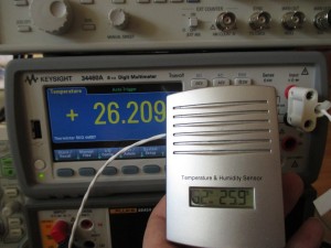
Recently I’ve found this piece of electronic on the dumpster, it was looking interesting – compact case with battery holder, LCD display, temperature and humidity sensor. It has also radio transmitter, but I’m not interested in it since I don’t have the receiver station. I decided to bring it back to life.It seems that was previously immersed in water – whole PCB was covered in white stains, in addition radio transmitter was covered in wax, that made removing of its components much harder. At first multimeter hasn’t shown shortcut of battery electrodes, but the device was drawing a lot of current, roughly 1A. I decided to clean it first using trisodium phosphate solution, then rework all of the joints with a lot of flux and clean it again. This fixed the problem of shortcut and the device started to work.
Unfortunately, while temperature readings were correlated with the environment, they were much too high. The temperature sensor is just a termistor, for those who want to see signals on its pins, below is a screen, as visible – current doesn’t flow through this element all the time, only, when a measurement is made. This will probably save some battery life. Nice.
It’s interesting that we may deduce how the measurement is done by the IC. It probably has a small capacitor loaded to Vcc, during the measurement, the capacitor is being connected to the sensor and discharged by it, the chip measures time to discharge the capacitor to 1V.
I don’t know, why the measurements were incorrect, maybe the IC or the thermostat was damaged by the humidity, maybe [this is cheap Chinese consumer electronic] manufacturer run out of the correct thermistors and replaced them with new ones with different curve, or maybe those were cheaper than originals. I don’t know. I decided to try to hack the curve of a thermostat by using serial and parallel resistors.
The problem is that I don’t have thermal chamber, so I can’t easily draw thermistor curve before and after the fix. I could improvise, but for such gadget I don’t care. I’ve removed thermistor from the PCB, and soldered on its place electrodes, then I placed the thermistor on a breadboard, and tried different values of resistors. The room temperature was between 21-25°C – I could modify it by opening a window – maybe not the best way, but it works. My whole room had become a temperature chamber 🙂
Finally, I’ve added two resistors, as visible below. It works for room temperature, but for outdoor use it’s still not good. Anyway, I will leave it as it is, at least for the moment.
For more detail: Hacking home weather station transmitter
- How did the author clean the water-damaged PCB?
The author cleaned the PCB using a trisodium phosphate solution, reworked all joints with flux, and cleaned it again. - Why were the temperature readings too high initially?
The measurements were likely incorrect due to damage from humidity, a different thermistor curve than expected, or cheaper replacement components. - What method was used to deduce how the IC measures temperature?
The author deduced that the IC uses a capacitor loaded to Vcc which discharges through the sensor, measuring the time to reach 1V. - Can the current flow through the thermistor element all the time?
No, the current only flows through the thermistor when a measurement is being made to save battery life. - How did the author calibrate the device without a thermal chamber?
The author removed the thermistor, placed it on a breadboard, and used room temperature variations by opening windows as a makeshift temperature chamber. - What specific components were added to fix the thermistor curve?
The author added two resistors, one in series and one in parallel, to modify the thermostat curve. - Does the fixed device work well for outdoor use?
No, while it works for room temperature, the device is still not good for outdoor use after the modification.