Summary of USB curve tracer for NPN transistors
This project builds a USB-based curve tracer for NPN transistors using a PIC18F4550 MCU and a Windows GUI to plot collector-emitter voltage (0–7.5V in 256 steps) vs collector current for seven base current levels (7 µA–60 µA). It uses an R-2R ladder to generate voltages, communicates over USB-HID (no special drivers), and is open source under GPLv3 with files on SourceForge. PCB construction is recommended for best results.
Parts used in the USB curve tracer for NPN transistors:
- PIC18F4550 microcontroller
- R-2R ladder resistive network
- Supporting passive components (resistors, capacitors)
- USB connector and wiring
- Power supply components (regulators, decoupling)
- Transistor test socket or mounting hardware
- PCB (recommended) or prototyping board
- Windows PC to run viewer application
Curve tracer is an electronic test instrument to analyze the characteristics of transistors and other discrete semiconductors. In this post we construct USB base curve tracer to analyze properties of NPN transistors. This curve tracer is build around Microchip’s PIC18F4550 MCU and it use simple Windows based GUI application to plot captured data of a transistor.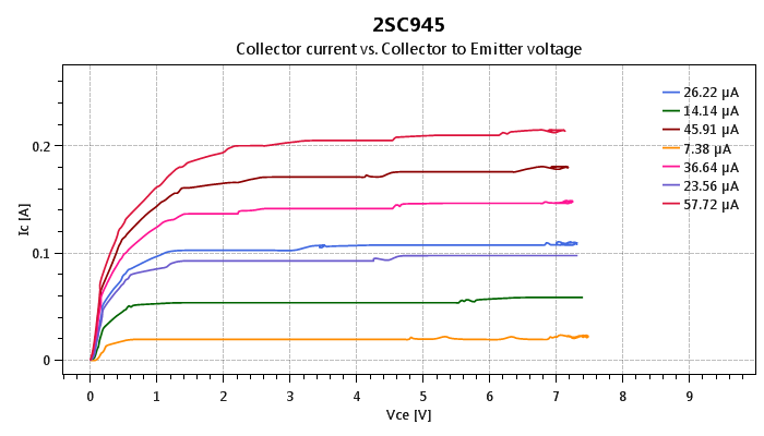
In this design PIC18F4550 MCU is used to establish USB connectivity, perform voltage readings and control current/voltage flow into the test subject. To minimize the cost and to make it simple, we use R2R ladder circuit to generate discrete collector-emitter voltage levels for the transistor on test. In each scan session collector-emitter voltage level get increase from 0V to 7.5V in 256 steps. In this design, “tracer” scans the transistor for 7 base current levels which are in between 7µA to 60µA. In viewer application collector-emitter voltage levels are plotted on x-axis and collector current is plotted on y-axis.
In current firmware, PIC18F4550 communicates with the PC over USB-HID class and because of that this may not need any special device drivers on host terminal. In most of Microsoft Windows operating systems the viewer application may be able to communicate with the device directly. Viewer application bundled in this project package are developed using Microsoft .net framework and it can run immediately on any new PC with minimum amount of prerequisites. Based on our experiences the most recommended operating system for this application is either Windows 7 or Windows 10.
To get the perfect results we highly recommended to construct this project on PCB. According to our experiences breadboards and veroboards may generate lot of noises and may finally leads to wrong output(s).
This is an open source hardware project and all it’s design files, source codes and compiled binaries are available to download at curvetracer.sourceforge.net. All the content of this project are released under the terms of GNU GPL version 3.0.
For more detail: USB curve tracer for NPN transistors
- What microcontroller is used in this curve tracer?
The design uses the PIC18F4550 microcontroller. - How is the collector-emitter voltage generated?
Collector-emitter voltage levels are generated using an R-2R ladder circuit. - What voltage range and resolution does the tracer use for Vce?
The tracer scans Vce from 0V to 7.5V in 256 steps. - How many base current levels does the tracer scan and what are they?
The tracer scans seven base current levels ranging between 7 µA and 60 µA. - How does the device communicate with the PC?
PIC18F4550 communicates with the PC over USB using the USB-HID class. - Does the viewer application require special drivers on Windows?
No special device drivers are required because the device uses the USB-HID class; the bundled viewer runs on Windows with minimal prerequisites. - Which Windows versions are recommended for the viewer application?
Windows 7 and Windows 10 are the most recommended operating systems for this application. - Is it better to build this on PCB or protoboard?
Building on PCB is highly recommended because breadboards and veroboards can introduce noise and lead to incorrect outputs. - Where can I get the design files and source code?
All design files, source code, and binaries are available at curvetracer.sourceforge.net and released under GNU GPL v3.0.