Summary of Automatic Pet Feeder
This project is an automatic pet feeder that uses the NXP PCA8565 RTC to trigger alarms via I2C. The PCA8565 alarm wakes a PIC16F684, which drives a DC motor (with PWM) to dispense food; an OBP625 opto-interrupter provides position feedback so the motor stops after a full turn. Time and alarm are shown on a 4-digit LED display (two HDSP-521E modules) driven by SAA1064. Time selection uses a 3-state slider on RA0/RA1, buttons on RA4/RA5 set time/alarm, and display power is switched off by MOSFET IRLML6402 controlled from RC2 after 10 seconds.
Parts used in the Automatic Pet Feeder:
- NXP PCA8565 real time clock (RTC)
- PIC16F684 microcontroller
- DC motor
- OBP625 opto-interrupter
- HDSP-521E 2-digit LED displays (two units)
- SAA1064 display controller
- MOSFET IRLML6402
- 3-state slider switch (connected to RA0 and RA1)
- Two push buttons (connected to RA4 and RA5)
- 32.768 kHz quartz crystal
This project is an automatic pet feeding system using NXP Semiconductors’ PCA8565. The PCA8565 is a CMOS1 real time clock and calendar optimized for low power consumption. A programmable clock output, interrupt output and voltage-low detector are also provided. All address and data are transferred serially via a two-line bidirectional I2C-bus with a maximum bus speed of 400kbps. The built-in word address register is incremented automatically after each written or read data byte. It provides a year, month, day, weekday, hours, minutes and seconds based on a 32.768kHz quartz crystal. It features alarm and timer functions, low current, and extended operating temperature range of -40 degrees Celsius to +125 degrees Celsius. It further contains an 8-bit year register that can hold values from 00 to 99 in BCD format. It also compensates for leap years, thus leap year correction is automatic.
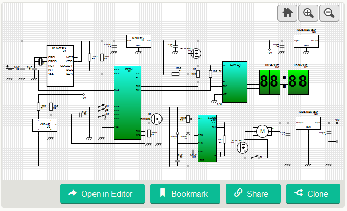
The electronic part of the device is just an alarm clock based on NXP PCA8565. The alarm initiates an interrupt that awakes the microcontroller. The later one sends a signal to the motor to control its forward and reverse mechanism. The dc motor must make a full turn and stop in the initial position to be ready for the next loading. This is achieved by an opto-interrupter OBP625, which provides a feedback to the microcontroller to stop powering the motor. The motor itself is controlled by PWM based on the timer IC in order to slow it down to a practical speed. The current time and the alarm time are displayed by a 4-digit LED display combined from two HDSP-521E 2-digit displays. Time to display is selected by a 3-state slider connected to pins RA0 and RA1 of PIC16F684. In the middle position of this switch both inputs are pulled up (internally). Two buttons at inputs RA4 and RA5 accomplish time setting and alarm setting. The LED display is controlled by SAA1064. The controller and PIC communicate via the I2C interface. The display is turned OFF after 10 seconds upon release of any button. This is achieved by simply turning OFF the controller and display power by a MOSFET IRLML6402 when the voltage on pin RC2 of PIC becomes 5V.
For more detail: Automatic Pet Feeder
- How does the feeder know when to dispense food?
The PCA8565 RTC triggers an alarm that generates an interrupt to wake the PIC16F684, which then controls the motor to dispense food. - Can the system detect motor position to stop after a full turn?
Yes, an OBP625 opto-interrupter provides feedback to the microcontroller to stop the motor when the initial position is reached. - How is the motor speed controlled?
The motor is controlled by PWM generated from a timer in the microcontroller to slow it to a practical speed. - What displays the current time and alarm time?
A 4-digit LED display composed of two HDSP-521E 2-digit displays shows the time, driven by an SAA1064 controller. - How do you select what time value to display?
A 3-state slider connected to RA0 and RA1 of the PIC16F684 selects the time to display; in the middle position both inputs are pulled up internally. - How are time and alarm settings adjusted?
Two buttons connected to RA4 and RA5 on the PIC16F684 are used to set the time and alarm. - Does the display stay on indefinitely after button use?
No, the display is turned off after 10 seconds upon release of any button by cutting controller and display power with MOSFET IRLML6402 when RC2 goes to 5V. - How do the RTC and microcontroller communicate?
They communicate via the I2C two-line bidirectional bus with up to 400 kbps speed. - Does the RTC handle leap years automatically?
Yes, the PCA8565 compensates for leap years automatically and stores year in an 8-bit BCD register from 00 to 99.