Summary of 8051 SRF04 ULTRASONIC DISTANCE METER CIRCUIT
This article details an 8051 microcontroller-based ultrasonic distance measurement system using the SRF04 transceiver. It explains the device's working principle, timing diagram, and calculation methods for distance in centimeters. The project integrates the 8051 controller with an LCD display to visualize measurements up to 10.7 meters, utilizing specific trigger and echo pulses.
Parts used in the 8051 SRF04 Ultrasonic Distance Meter:
- 8051 Microcontroller
- SRF04 Ultrasonic Transceiver
- LCD Display
- Circuit Schematic
- Source Code Files
8051 srf04 ultrasonic distance measurement application also contains information about the different controllers and this information can be useful for applications 8051 microcontroller distance measurement using ultrasonic transceiver done. Studies, using microcontrollers 8051 with the help of ultrasonic distance… Electronics Projects, 8051 SRF04 Ultrasonic Distance Meter Circuit “avr project, microcontroller projects,
8051 srf04 ultrasonic distance measurement application also contains information about the different controllers and this information can be useful for applications
8051 microcontroller distance measurement using ultrasonic transceiver done. Studies, using microcontrollers 8051 with the help of ultrasonic distance measurement includes the transceiver. A system ultrasonic transceivers, LCD et al 8051 microcontroller is used.
Before initiating operation of the system used in the system of the working principle of the ultrasonic transceiver is deemed useful to give a brief. authors :Murat FETTAHOGLU Faruk YILDIRIM
SRF04 ULTRASONIC TRANSCEIVER
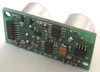
To a distance of 10.7 meters maximum results. Has a low current consumption. Minimum sensitivity distance is 26cm. Is preferred because the smaller size modules.
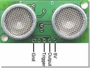
SRF04 ‘front side of Figure 2 are given in. As shown in Figure 4 has the port. Among them, 2 percent supply (+5 V), the other two pulse outputs (pulse echo output) and trigger input (input trigger pulse) is.
SRF04 TIMING DIAGRAM
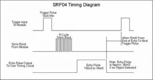
Srf04 The working principle is briefly as follows: SRF04 ‘reputation minimum 10us to start working a trigger pulse as shown in the diagram SRF04’ reputation is applied to the trigger input. After applying these pulses SRF04 sends out ultrasonic waves and generates.
340metre/sani is known that the speed of sound in air, bounced off the surface of these sound waves are sent back period is calculated. This period is known, the sound velocity on the basis of the calculated distance from the apparatus body.
If done the calculations, pulse output from the pulse duration in the availability USN 58 ‘E division (cm = usn/58) can be calculated in centimeters away. If 18ms from If no pulse is produced on a larger object is detected, the output value of 36msn SRF04 again to drop to 0 volts level.
8051 SRF04 Ultrasonic Distance Meter Circuit schematic 8051 source code etc. files
FILE DOWNLOAD LINK LIST (in TXT format): LINKS-6945.zip
Source: 8051 SRF04 ULTRASONIC DISTANCE METER CIRCUIT
- What is the maximum distance this system can measure?
The system can achieve results up to a distance of 10.7 meters. - How does the SRF04 start its operation?
The module requires a minimum 10us trigger pulse applied to the trigger input to start working. - What formula calculates the distance in centimeters?
The distance is calculated by dividing the pulse duration in microseconds by 58 (cm = usn/58). - What is the minimum sensitivity distance of the SRF04?
The minimum sensitivity distance is 26cm. - Does the system use an LCD display?
Yes, the system includes an LCD to display the measured data alongside the 8051 microcontroller. - What happens if no pulse is produced after 18ms?
If no pulse is produced within 18ms, it indicates a larger object was detected, and the output drops to 0 volts level. - What are the voltage requirements for the SRF04 supply?
The supply port requires +5 V. - Can I download the source code and schematic files?
Yes, circuit schematics and source code files are available for download in a ZIP format.