Summary of 60MHz Frequency Meter / Counter using pic microcontroller
Summary: A 60MHz Frequency Meter/Counter kit measures 10Hz–60MHz signals with 10Hz resolution, using a PIC16F628A MCU, LCD, onboard amplifier and TTL converter for high sensitivity. Powered from 6–15V, it consumes ~80mA with backlight. The detachable 16x2 LCD connects via 16-pin headers; adding a prescaler (MC12080) extends range to several hundred MHz or ~1.2GHz.
Parts used in the60MHz Frequency Meter / Counter:
- 16x2 LCD Display with Green/Blue Backlight
- PIC16F628A Pre-programmed MCU
- PCB
- 18-DIP IC Socket
- 4.000MHz Crystal
- LM7805 5V Voltage Regulator
- 1x16 Gold Plated Female Header (for PCB)
- 1x16 Gold Plated Male Header (for LCD)
- 2x 1x2 Gold Plated Male Header (Power & Frequency Input)
- BF199
- 10uH Inductor (brown black black silver)
- 10K Trimmer (103)
- 10K 1% Metal Film Resistor
- 2x 470 1% Metal Film Resistor
- 10 1% Metal Film Resistor
- 2x 100nF Ceramic Capacitor (104 / 100n)
- 2x 10pF Ceramic Capacitor (10)
|
|
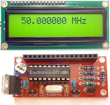
60MHz Frequency Meter / Counter measures frequency from 10Hz to 60MHz with 10Hz resolution. It is extremely useful bench test equipment for testing and measuring frequency of oscillators, transmitters, radio receivers, function generators, crystals, etc. Counter provides exceptionally stable readings and has excellent input sensitivity thanks to onboard amplifier and TTL converter. It can be even used for measuring weak signals from crystal oscillators. With the addition of simple prescaller it is possible to measure frequency up to 1GHz or more. Counter’s measuring range has now been extended form 50MHz up to 60MHz.
LCD display is connected to PCB by 16-PIN male & female header and is easily detachable from the main board. 16-PIN Male Header must be soldered to LCD display. 16-PIN Female Header must be soldered to PCB.
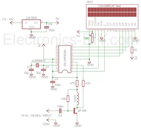
Components Placement
When counter is powered “60 MHz Counter” message should be displayed on LCD display. A second after meter should be ready to measure the input frequency with “0.000000 MHz” being displayed on the display. If no text is visible adjust the LCD contract by trimming 10K trimpot counter-clockwise.
 Frequently Asked Questions
Adjust LCD contrast by turning P1 trimmer counterclockwise, then turn it slowly clockwise until text is shown on LCD.
What is the display resolution of 60MHz Counter kit?
60MHz Counter kit measures input frequency with impressive 10Hz resolution.
Is it possible to use 60MHz Counter kit to measure output frequency of 88-108MHz FM Transmitter?
By adding simple MC12080 prescaler circuit pictured below in divide by 10 configuration it is possible to measure 0-600MHz frequency. Connect prescaler between 60MHz Counter’s input and transmitter’s RF Antenna output. After adding prescaler 108.55 MHz frequency will be displayed as 10.855000 MHz. By adding MC12080 prescaler circuit in divide by 20 configuration it is possible to measure frequency up to 1.2GHz.
- What voltage supply does the 60MHz Frequency Meter / Counter require?
The kit requires a voltage supply of 6V to 15V as stated in the technical specifications. - What is the current consumption with the LCD backlight?
Current consumption is approximately 80mA with the LCD backlight. - What frequency range can the counter measure without extras?
The counter measures from 10Hz to 60MHz. - What measurement resolution does the counter provide?
The measurement resolution is 10Hz. - How do I fix a blank LCD after powering the kit?
Adjust the LCD contrast by turning the P1 10K trimmer counterclockwise, then slowly clockwise until text appears. - How is the LCD connected to the PCB?
The LCD attaches via a 16-pin male header soldered to the LCD and a 16-pin female header soldered to the PCB, making it detachable. - Can the counter measure higher frequencies like FM broadcast outputs?
Yes, by adding an MC12080 prescaler in divide by 10 configuration you can measure up to 600MHz (displaying 108.55 MHz as 10.855000 MHz). - How can the measuring range be extended up to about 1.2GHz?
Use the MC12080 prescaler in divide by 20 configuration to measure frequencies up to approximately 1.2GHz. - What message should appear on the LCD when the counter is powered?
When powered the LCD should display the message 60 MHz Counter, then show 0.000000 MHz when ready to measure.