Make your own PIC programmer for your computer’s parallel port. This is a variation of David Tait’s classic design. It is very reliable and there is good programming software available for free. I like IC-Prog and PICpgm programmer. Best of all, it uses just two voltage regulator and 5 transistors!
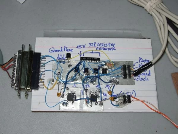
*** I added a pic of the final result, and pics of my new mini-programmer with a clear top. Click the smaller images below!
** This is a new variation and it didn’t work 100% correctly on the first attempt. I guess I got ahead of myself.. I have built several variations, and I thought I was on top of things. 🙂 There are a couple of changes, but everything worked out in the end. I had to add an additional npn transistor and change a couple of resistor values. These changes are already reflected in this list, but are not updated in all the pics. See step 7 for pics of the software I use and how to set up the programmer.
You need:
A male DB25 socket
4x NPN transistors, such as the 2n3904
1x PNP transistor, such as the 2n3906
1x 7805 voltage regulator
1x LM317 voltage regulator (and appropriate resistors to make 12.5V)
1x 10k SIP resistor network
4x 10k resistors
1x 22k resistor* update for step 3
1x 5k resistor
1x 1k resistor* update for step 3
1x machined-pin chip socket
soldering iron, protoboard, wraping wire, wrapping tool, glue gun.
Step 1: Index card
If you have copper tape, lay a strip down as a ground plane. If not, put a row of staples into the paper along one edge and solder them together.
Then bend the legs of the SIP resistor network, and glue as shown.
Step 2: ICSP port
Make an ICSP port with part of a chip socket, like this. Carefully bend the pins at a right angle.
Now glue port down.
Now is also a good time to glue your transistors on. You can also solder the emitter of your npn transistors to the ground plane, now. I have labelled each transistors purpose here.
The three npn transistors will be wired as inverters. They will essentially “take power away” from their respective pullup resistor when a current is placed onto their base pin.
The PNP transistor (upside down) will control the programming voltage. It is also going to invert it’s signal.
**EDIT: I just realized an omission in this design. There should be one additional npn transistor that is used to drive the PNP transistor. This will buffer your computer port from the voltages at the pnp’s base. My bad. This will also uninvert the signal. See step 8.
Step 3: Base resistors
I used 10k base resistors. Solder where circled. I messed up the pnp transistor in this pic. Disregard the whited out area.
**EDIT: the base resistor for the “data in” tranny should be 22k. Also, data out tranny should not be pulled up with the 10k resistor network. Instead, pull it up with a 1k resistor. I just realized that these two resistors will form a voltage divider, and if each is 10k data high will be 2.5V… no good. (Alternatively, you could just leave things the way they are, but connect Data Out transistor’s collector to all remaining 5 10k pullups. This makes the divider 2/10, which should still suffice. On my particular circuit, that’s what I did, and it registers 4.24V as high, which should be enough.)
Picture 2:
The pnp transistor gets two base resistors wired as a divider. Solder the 10k resistor between emitter and base. Solder one end of your 5k (actually I used 3.3k cuz I had it lying around) to the base. You can connect collector to Vpp pin, now, since it is close.
Eventually, you will be connecting the emitter to 12.5V source. The 10k resistor keeps the base high – thus programming voltage off. When pin 5 of your parallel port goes low, it pulls the base low, via the 5k resistor.
The schemmy I used also showed a 10k resistor between collector and ground. I’m not sure what it’s for. I think it is to ensure that the PIC’s MCLR pin does not float. But that would be silly, since MCLR is usually going to be connected to an external pullup, anyway. In addition, MCLR pin is an active sink of a few microamps. It doesn’t float. At any rate, I have recklessly omitted this resistor. Bonus points for anyone who can tell me why this is bad idea.
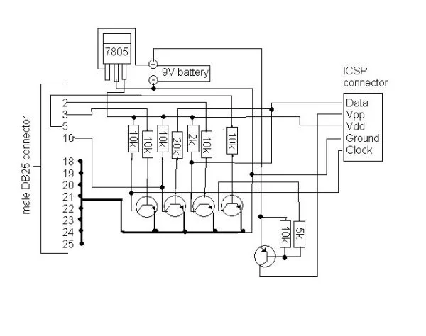
For more detail: 5 transistor PIC programmer *Schematic added to step 9!