
Summary of 4 Channel RF Remote Controller
This article describes a 4-channel RF remote control system using Princeton Technology's PT2262 encoder and PT2272-M4 decoder ICs. The transmitter operates on 5V–12V DC, while the receiver requires 5V DC. Pressing switches triggers the encoder to transmit address and data bits via an RF module. The receiver decodes the signal if jumper settings match, activating TTL-level outputs and a VT LED. The system supports 6561 unique address combinations to prevent code collisions.
Parts used in the 4 Channel RF Remote:
- PT2262 Encoder IC
- PT2272-M4 Decoder IC
- RF Transmitter Module (ASK RF TX)
- RF Receiver Module (ASK RF RX)
- Tact Switches (SW1-SW4)
- Jumper Pins (J1-J8)
- VT LED
- Relay Board Interface
4 Channel RF remote built using PT2262 and PT2272-M4 IC from Princeton technology. PT2262 used as Encoder (Transmitter) and PT2272-M4 Decoder (Receiver) ICs are heart of the project. The receiver provides 4 channel Momentary outputs. All outputs are TTL level can be interface with other circuits or relay board. Transmitter works with 5V to 12V DC. Receiver works with 5V DC.
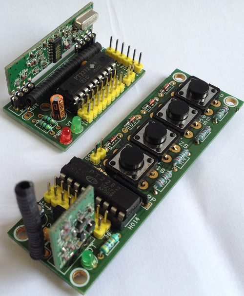
When any of SW1-SW4 (S1-S4) tact switch is pressed the, power is applied to encoder IC and RF transmitter module, the encoder then starts scanning Jumper J1-J8 and transmitting the status of the 8 bits address and data serially. The decoder IC receives the data and compares two times with J1-J8 address jumpers and provides outputs high and also VT LED goes On, if the data is Valid and address of Transmitter and Receiver are same. It is important to have same jumper settings J1-J8 at transmitter and receiver to pair both. Multiple remote can be used to control devices at same location by changing the address codes. All address is Tri-State and offers 6561 combinations.
Encoder – Transmitter (PT2262)
PT2262 is a remote control encoder paired with PT2272 utilizing CMOS technology. Its encode data and address pins into a serial coded waveform suitable for RF modulation. Circuit uses 8 bits of tri-state address pins providing up to 6561 address codes, thereby, drastically reducing any code collision and unauthorized code scanning possibilities.
PT2262 encodes the code address and data set into special waveform and outputs it to the DOUT when TE is pulled to low. The wave is fed to RF modulator (ASK RF TX Module) for transmission. The transmitted radio frequency is received by RF demodulator (ASK RF RX Module) and reshaped to special waveform. PT2272 is then used to decode the waveform and set the corresponding output pins. Thus completing a remote control encoding and decoding function.
For More Details: 4 Channel RF Remote Controller
-
What is the heart of this project?
The PT2262 Encoder and PT2272-M4 Decoder ICs from Princeton Technology are the core components. -
How many channel momentary outputs does the receiver provide?
The receiver provides 4 channel Momentary outputs that are TTL level compatible. -
Can multiple remotes be used at the same location?
Yes, multiple remotes can be used by changing the address codes set on the jumpers. -
What voltage range does the transmitter work with?
The transmitter works with a DC voltage range of 5V to 12V. -
Why must J1-J8 settings be identical on both units?
Both units need the same jumper settings to pair correctly so the decoder recognizes the valid address. -
How many unique address combinations does the Tri-State offer?
The Tri-State address pins offer 6561 combinations to reduce code collision. -
What happens when the data is valid and addresses match?
The decoder sets the corresponding output pins high and the VT LED turns on. -
Which technology is used for encoding and decoding?
CMOS technology is utilized by the PT2262 and PT2272 ICs for encoding and decoding functions.

