Summary of 4.5Amps Bipolar Stepper Motor driver based on TB6600
The article describes the TB6600 4.5A Bipolar Stepper Motor Driver, designed for Nema17/23/34 motors with 4, 6, or 8 wires. It features auto half-current control, thermal shutdown, and micro-stepping via DIP switches. The driver supports forward/reverse rotation and includes optical isolation for inputs like Enable, Direction, and Step Pulse. Applications range from CNC machines to robotics, emphasizing safety precautions regarding power connections and current settings using onboard potentiometers.
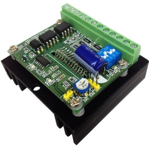
Parts used in the TB6600 Stepper Motor Driver Project:
- TB6600 IC
- Nema17, Nema23, Nema34 bipolar stepper motors
- Current sense resistors
- Preset Potentiometer (PR1)
- 4-way DIP switch
- Output Fault Monitor LED indicator
- On Board Power LED indicator
- On Board step pulse input indicator
- Large capacitor
- CN7 (CT) onboard connector
Features
- Based on Single chip and Second chip for auto half current control
- Suitable for Nema17, Nema23, Nema34 bipolar stepper motors
- Suitable for 4Wires, 6 wires and 8 wires stepper motor.
- Forward and reverse rotations available
- Selectable Phase (Micro-step) drives 1/1, 1/2, 1/4, 1/8, and 1/16
- Maximum Input supply 42V DC Minimum Input supply 10V DC
- Output current 4.5Amps
- Output Fault Monitor LED indicator
- On Board Power LED indicator
- On Board step pulse input indicator
- Standby auto half current reduction circuitry onboard
- Built in Thermal shutdown (IC)
- Built in under voltage lock out (UVLO) circuit (IC)
- Built in over current detection (ISD) circuit (IC)
- Large capacitor to handle inrush current
Applications
- Robotics
- Large format Size Printers
- CNC
- Routers
- 3D Printers
- Machine Automations
- Camera Pan Tilt Heads
- Slot Machine
- Vending Machine
Heat-sink and Thermal Shutdown
The board has current sense resistors and these resistors has been set as per maximum load current 4.5A, If you use lower current motor, please set the PR1-Preset ( Potentiometer) to the required level for the motor. At maximum current load TB6600 IC will overheat in some time and a RED LED turns on. This LED goes off once the temperature falls to a safe operating level.
Micro Stepping
A 4way DIP switch is used to set the micro step modes (Full, Half, Eight, Sixteenth), please see the table for Micro step settings. DIP Switch settings should be changed when power is off so the correct selection is active at power up.
Step Pulse
Minimum positive duty cycle of the input step pulse should be 2.2us and required 5V (TTL) signal. A positive going pulse on the step input activates a step operation.
Current Settings
Average drive current can be set using a Preset (On Board PR1 Potentiometer). CN7 (CT) onboard connector is provided to measure the voltage to set the motor current (torque). Voltage range to set the torque 0.3V to 3.5V
Cautions
- Never connect or remove supply wires, motor wires, or input interface when power is on, this can cause damage to drive.
- Switch the Power to set the Micro stepping
- Before using this drive, please have proper information about stepper motors, Motor impedance, Inductance and other specs.
Inputs
All Inputs are optically isolated to prevent the device for any kind of noise, short circuits.
- Enable: Required 5V DC input, Set high Input disabled the drive, Set low input Enable the drive
- Dir.: Required 5V DC input, Set high Input CW Rotation, Set low input CCW Rotation, Direction of the motor depends how stepper motor has been wired.
- CLK: Step Pulse required 5V DC TTL pulse
Outputs
4 Wires, 6 Wires, 8 Wires Motors can be used with this drive in bipolar mode.
On board LED for Alert
4XDIP SWITCH
SW4 (LATCH): ON=Automatic Return if Thermal Shutdown Or Over Current Detection OCCURS
SW4 (LATCH) : OFF= On Fault condition required power on/off
For more detail: 4.5Amps Bipolar Stepper Motor driver based on TB6600
- What is the maximum input supply voltage?
The maximum input supply is 42V DC. - How do you set the micro-step modes?
A 4-way DIP switch is used to set the micro-step modes such as Full, Half, Eight, and Sixteenth. - Can this driver handle 6-wire stepper motors?
Yes, it is suitable for 4-wires, 6-wires, and 8-wires stepper motors. - What happens if the drive overheats?
A RED LED turns on when the IC overheats, and it goes off once the temperature falls to a safe operating level. - How is the motor current adjusted?
Average drive current is set using the On Board PR1 Potentiometer by measuring voltage at the CN7 connector. - Does the driver support automatic return after a fault?
Yes, setting SW4 LATCH to ON enables automatic return if Thermal Shutdown or Over Current Detection occurs. - What signal type is required for the Step Pulse input?
A positive going 5V TTL pulse with a minimum duty cycle of 2.2us is required. - Are the inputs protected against noise?
Yes, all inputs are optically isolated to prevent noise and short circuits.