Summary of Serial LCD Controller
The article discusses a flaw in a serial LCD controller design for a 4x20 Hitachi chipset LCD, where the controller only works via computer connection, not microcontroller due to a circuit issue involving a transistor and a 10K resistor. Solutions include cutting the resistor connection or adding a jumper for communication mode selection. Updated schematics, code (ported to PicBasic Pro for PIC16F628A), and PCB files fixing design errors are provided. The project aims to support multiple LCD types and is being upgraded to use PIC16F88 for added functionality.
Parts used in the Serial LCD Controller Project:
- PIC16F628A Microcontroller
- Hitachi 4x20 line parallel LCD display
- 10K resistor (R8)
- Transistor (type unspecified)
- Jumper (for inverted/non-inverted RS232 control selection)
- Power regulation board components (unspecified)
- PCB board for LCD and power
I discovered a flaw in the current design that will only allow the controller to work with a connection to the computer and not to a microcontroller. I’ve updated the schematic below and will fix the controller design. I’ve added a project file below that also includes the fixed schematic.

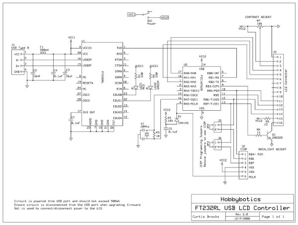
If you look at the schematic you will notice that when you set the jumper to non-inverted so you can connect to a microcontroller for serial control it will not work. The reason is in the way I designed the circuit for both inverted/non-inverted RS232 control. Looking at the transistor in the circuit, the collector is held high through a 10K resistor. The collector feeds to the Rx pin on the PIC. When you set the jumper to non-inverted and attempt to send data to the PIC it won’t work because the line is always tied high through R8 to 5V.
There is a fix and I have included it in the archive file below. There are two ways to do this:
1. If your board is already built and your intentions are to only use this LCD in a finished design and not attached to the computer then, snip the connection from R8 to 5V and the controller will only work in the non-inverted configuration.
2. Look at the included schematic in the archive and add the shown J2 jumper to your design which will allow you to select between the two types of communication.
04 October 2009
I have redesigned the LCD Controller and updated the code. The new schematics and code can be found below. I ported the code from MBasic to PicBasic Pro. I’ll leave the old code up for those who still want it.
The files below are from a project that I have been working on for a serial LCD controller for a 4×20 line parallel display with the Hitachi chipset. I am also working on a USB design. In the picture of the demo board there is a wire jumper installed. This is because I screwed the pooch and somehow missed a crossed trace. I had to repair the board. In the download files the PCB files have been fixed. I’ll upload some video of functionality when I get a chance.
The code and project files have been posted in the download links.
Project file downloads
Old code:
Power regulation board schematic
Demo application with sourcecode
05 October 2009 Project Files
PicBasic Pro PIC16F628A code for 16×2 character LCD
PicBasic Pro PIC16F628 code for 16×2 character LCD
PicBasic Pro PIC16F628A code for 20×4 character LCD
Archive containing test application, schematic, and PCB (ExpressPCB)
PicBasic Pro LCD Controller interface to Parallax GPS receiver
Ensure all the files are unzipped to the same folder. The include file that is referenced contains the fuse settings for the selected PIC chip.
I will be uploading a version soon that allows the type of LCD to be set. This will allow the same controller to be used for a variety of LCDs. I can’t squeeze that functionality into a PIC16F628 chip without removing some of the current functionality. So, I am porting that over to a PIC16F88.
More to come…
Breadboard testing of the LCD controller
For more detail: Serial LCD Controller