Summary of Programmable digital timer switch using a PIC Microcontroller
This project presents a programmable digital timer switch using the PIC16F628A microcontroller to control electrical appliances via a relay. It supports setting customizable on/off times up to 99 hours and 59 minutes. The device features a 16×2 LCD for status display and uses four push buttons for user input. The relay is driven by a PN2222 transistor controlled by the microcontroller, and the circuit includes a piezo buzzer for audible alerts. Power is supplied by a 9V adapter regulated to 5V using an LM7805 IC.
Parts used in the Programmable Digital Timer Switch:
- PIC16F628A microcontroller
- 5V relay
- PN2222 transistor
- 16×2 character LCD (4-bit mode)
- Four push buttons
- Piezoelectric buzzer
- LM7805 voltage regulator IC
- 9V DC wall adapter
- 39 Ohm resistor (for LCD backlight)
- General purpose prototyping circuit board
Circuit Design
The circuit diagram of this project is shown below. A 5V relay is driven by a PN2222 transistor that is controlled by RB3 pin of PIC16F628A. Digital inputs from the 4 push buttons are read through port pins RA2, RA3, RA4, and RB0. The functions of these push buttons are discussed in the operation section below. A standard 16×2 character LCD is used in the project to display the device status, program menu and time. The LCD is operated in 4-bit mode, therefore, only 6 I/O pins of PIC16F628A are required to drive it. A piezoelectric buzzer provides audible tone when the timer is started and stopped. It also beeps when the device is turned on or off. The + 5V power supply for the circuit is derived from a LM7805 regulator IC. The input to the regulator is given from a 9V DC wall adapter.
In the circuit diagram, the pins 15 and 16 of the LCD are shown open. These pins are available only in those LCDs that have a back light illumination LED. The pins 15 and 16 are the anode and the cathode of the LED. If your LCD has the back light LED, you can connect these pins to the power supply terminals with a 39 Ohm resistor in series. The backlight LED enhances the readability of the LCD display in low illumination condition.
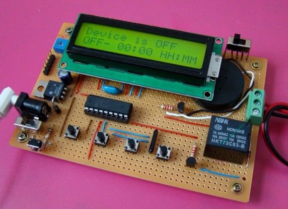
The complete circuit soldered on a general purpose prototyping circuit board is shown below.
Operation of the timer
The timer gets inputs from the 4 push buttons. Their functions are described as follows: